Robot courier
We assemble a wheeled robot and teach it to drive along a line, find objects and deliver them.
Assembling the robot and reviving the board
Assemble the robot and test each installed component with a diagnostic sketch.
Lesson result
Assembled robot: both motors are checked in both directions and stop, both line sensors react to white and black. The test results are recorded in a log.
You will learn
- Assemble the robot chassis according to the instructions and check each unit.
- Distinguish between the front, back, left and right sides of the robot.
- Upload the program to the Arduino and explain what setup() and loop() do.
- Check both motors, their stop and both line sensors; distinguish the program command from the observed result.
Need to know
Nothing - this is the first lesson.
Will need
Why this lesson
Throughout the course you will work with one robot - your own. Today you will assemble its chassis, install the “brain” of the robot - the Arduino board - and write the first program. By the end of the lesson, you will have tested each unit installed and recorded that it actually works.
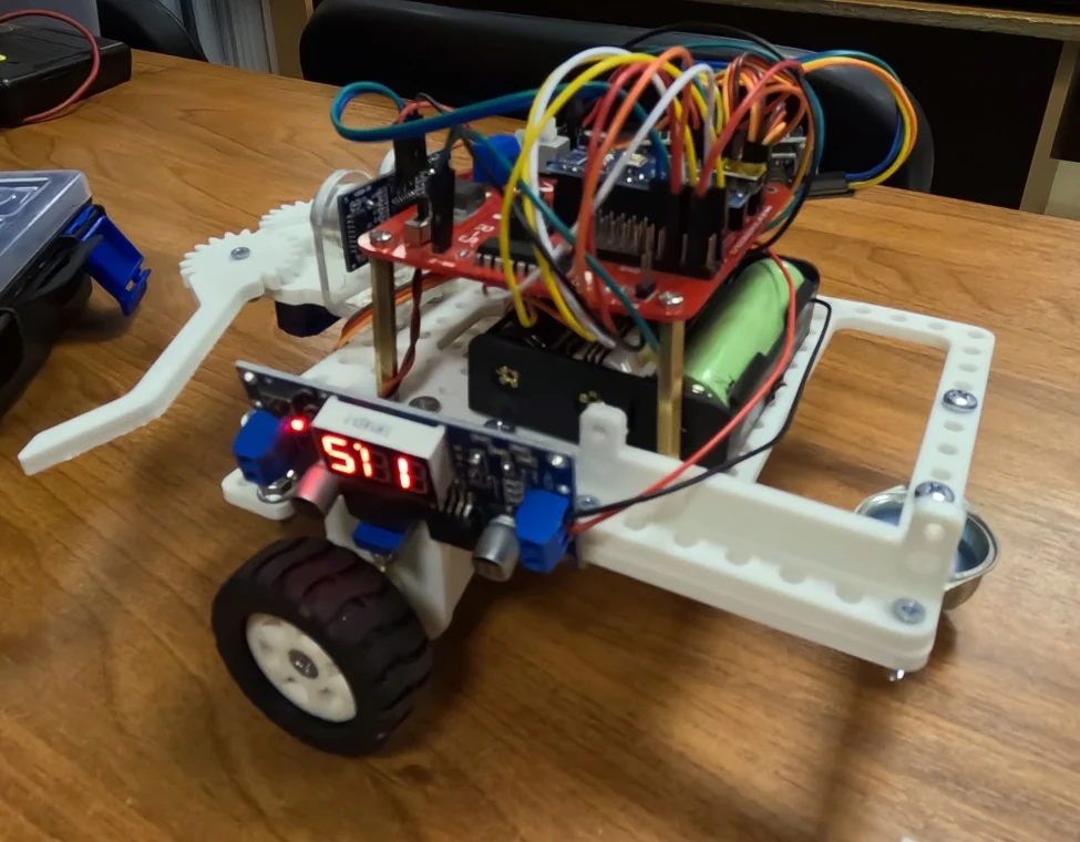
While assembly is in progress, the battery compartment is disconnected and the USB cable is not connected to the computer. The battery compartment is connected to the shield in advance by an adult. You turn the motors on and off only with a switch.
Assign roles
3 minWhat should a robot do. First, the robot needs to correctly execute individual commands: rotate each wheel, stop and report sensor readings. Before our independent trip, we will check each component in turn to look for the cause of the error in one place.
What we use and how it works. Arduino Uno is executing the program. The L298P driver uses its signals to control the power supply to the motors: the DIR pin sets the direction, PWM - the proportion of power supply time. The motor converts electrical energy into rotation, and the wheel into movement. Two reflection sensors on the bottom help distinguish between a light surface and a black line.
How to link a dimension to an action. The command and the result are two different things. The inscription in the monitor means that the program has reached printing; We check the rotation with our eyes. On the stand, we will check both directions of each wheel and the stop, then compare the readings of the sensors above the white and black cards. This way we’ll find out exactly how our robot is assembled.
You are working together. One - Pilot: holds parts and a screwdriver. Second - Navigator: reads the step out loud, provides the details and checks the result using the picture.
- Decide who starts as Pilot.
- After each part that is secured with screws, switch roles.
Everyone knows their role. The navigator holds the instructions, the pilot holds the instrument.
Lay out the parts
7 minFind every part before assembling. This way you won’t confuse similar parts and will immediately see if something is missing.
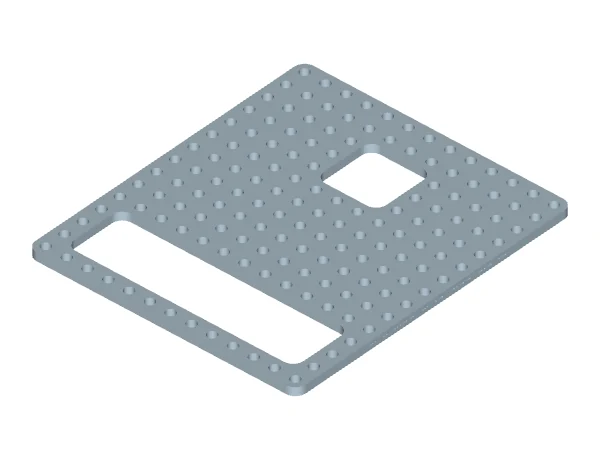
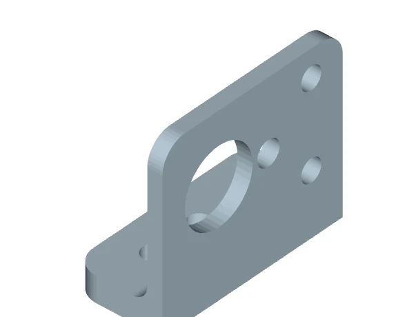
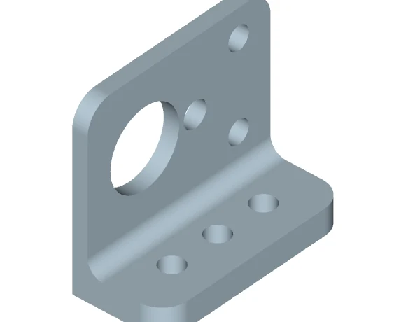
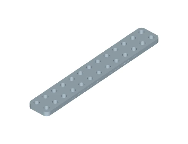
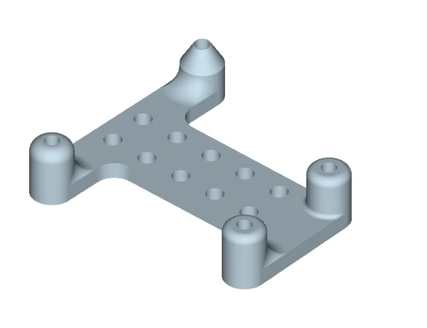
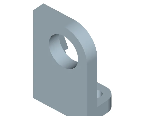
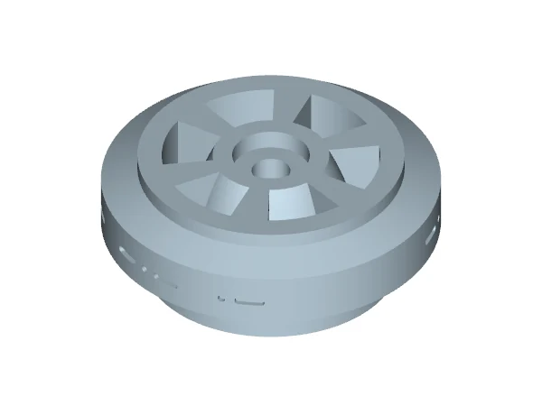
- Arrange the printed parts in a row, like on cards.
- Find two motor brackets. They are similar, but mirrored: put them side by side and look - the shelves face in different directions.
- Place the purchased parts nearby: Arduino, motor shield, two motors, a ball joint, two line sensors, a battery compartment and bags with fasteners.
All the details are in front of you. You can show both mirror brackets.
Hint: Missing part
Don't replace it with something similar. Check the package with cards again; If there are no details, tell an adult.
Practice on one screw
4 minAlmost all parts of the robot are held on by screws and nuts. Let's assemble one connection on the table.
- Take a screw, two washers and a nut from the Training bag.
- Place the washer on the screw, slide the screw through the two pieces, put the second washer on and screw the nut on with your fingers.
- Hold the nut with your finger and tighten the screw with a screwdriver. Stop as soon as the parts stop moving.
Connection order: screw → washer → part → part → washer → nut. The parts don't wobble.
How it works: Why you can’t tighten it with all your might
The parts are printed from plastic. If you overtighten the screw, the plastic will press through or crack. A sign of overtightening - the part bends or turns white around the screw.
Agree where in front
3 minSo that “left wheel” always means the same thing, let’s mark the front of the robot.
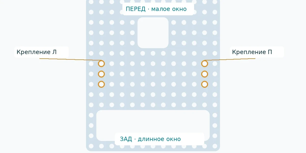
- Lay the base flat: a small square window is further away from you, a long rectangular window is closer.
- Far side - before. Stick a paper forward arrow on it.
- Define left and right as the driver who sits in the robot and looks in the direction of the arrow.
There is a forward arrow on the base. You both show the left side of the robot the same way.
Attach the motor brackets
8 minBrackets hold the motors from the bottom of the base.
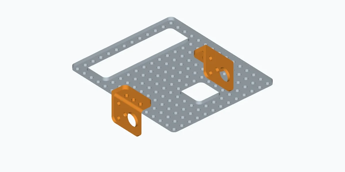
- Turn the base over so that the arrow remains visible from the side.
- Place the brackets on the bottom side as shown. Big round holes look out out - the wheel axles will go there.
- Insert the screws from above and fit the washers and nuts underneath. Start all screws loosely by hand, then tighten them.
The two brackets are facing each other, the large holes are on the outside. The brackets do not swing.
Install the motors
8 minThe motor axis is a rotating rod on which the wheel fits. It should come out through the hole in the bracket.
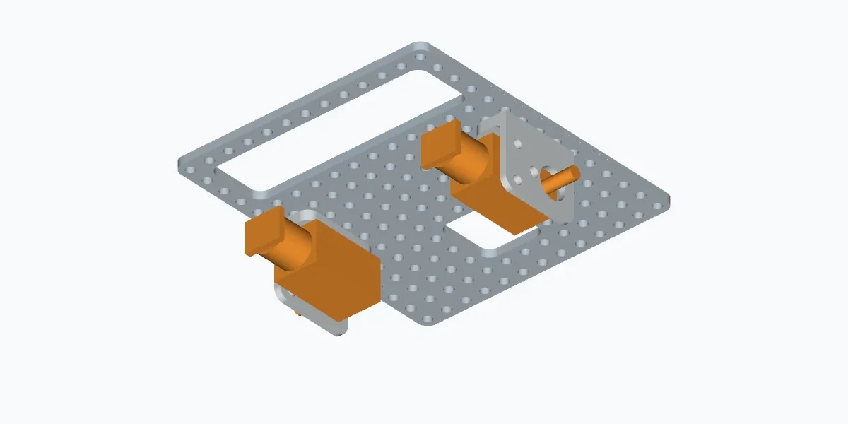
- Attach the first motor to the bracket from the inside. The axis passes through a large hole outward.
- Secure the motor with the screws from the Motors package. Hold the motor with your hand while you tighten it.
- Also install the second motor.
- Label the wires: L - left motor, P - right. Check the forward arrow.
Both motors are held tightly, the axes point left and right, the wires are labeled.
Hint: The motor does not fit into the bracket
Don't press or file. Check if this is the right bracket: maybe you took a mirror one for the other side.
Put on the wheels
5 min- Align the wheel hole with the motor axle. The shape of the hole must match the shape of the axis.
- Put the wheel on while holding the motor by the housing. Don't hit the wheel.
- Look from the side: the wheel should not touch the bracket or base.
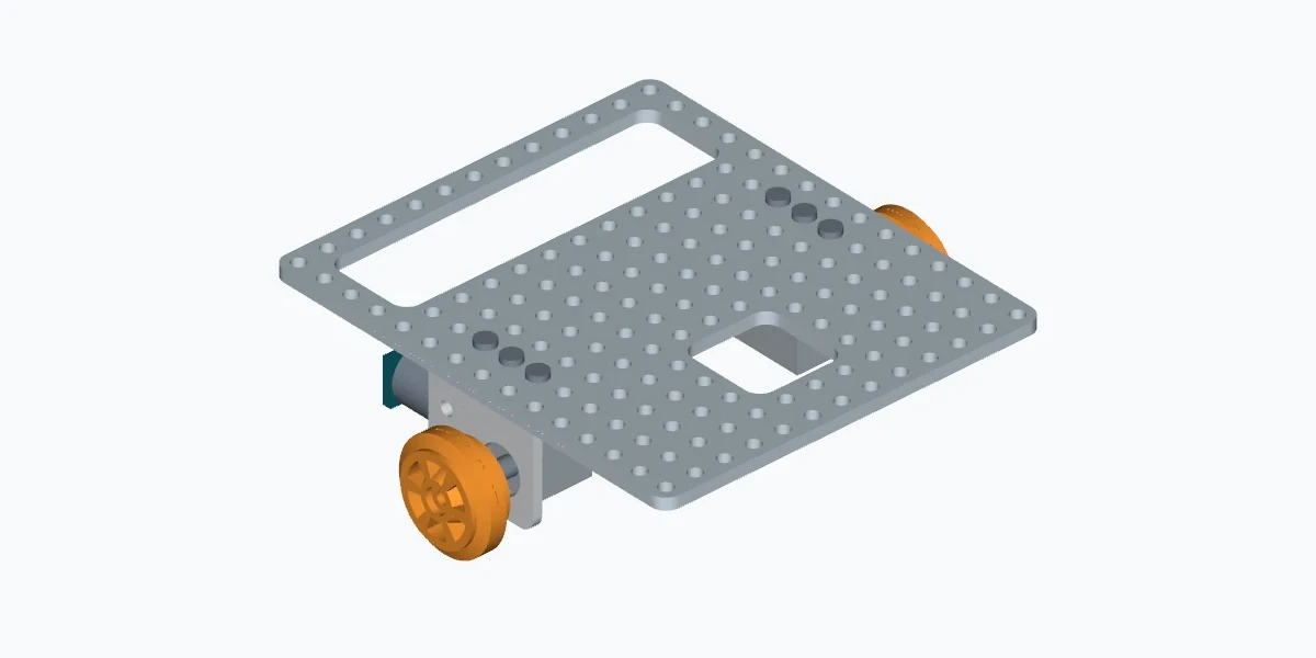
Two wheels stand on axles and do not touch anything.
Add a back support and check the robot
7 minThere are two wheels, so the robot needs a third support point at the back - a ball joint.
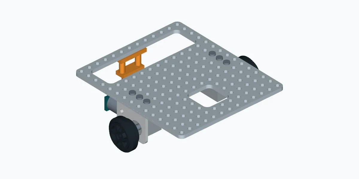
- Attach the ball joint from below to the back side of the base. The racks from the “Support” package are selected in height.
- Place the robot on the table. It should stand exactly on two wheels and a support.
- Gently rock the robot. Nothing should be loose.
The robot stands stable and level. The chassis is ready.
Install Arduino
6 minArduino is the “brain” of the robot. The board lies on the holder so that its contacts from below do not touch the screws.
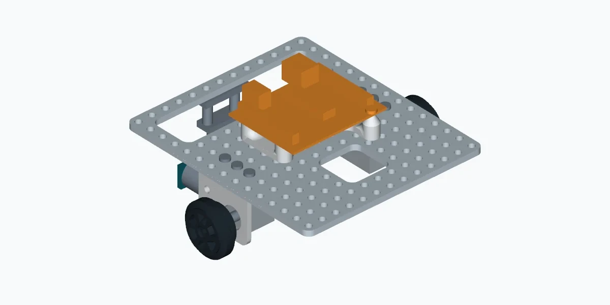
- Secure the Arduino holder in the center of the base with the posts facing up.
- Place the board on the stands so that the USB connector is at the edge and can be reached.
- Secure the board with screws. Tighten them one by one, little by little.
The board lies flat and does not touch the base screws. The USB connector is free.
Prepare your computer
5 minPrograms for the robot are written in MyRobotica. It has lessons and a code editor.
- Connect the USB cable to the Arduino and to the computer. The battery compartment of the motors remains disconnected.
- Open MyRobotica course "Robot Courier" and lesson 1.1. Open the lesson project.
- On the right side of the button Upload to robot choose your real robot. B More about communication check the board Arduino Uno and its port.
- Leave empty functions in the editor
setup()andloop()and save the program.
The ON power indicator on the board is lit. In MyRobotica, the tutorial project is open, a real robot with an Arduino Uno board is selected, and its port is visible.
Hint: I don't see the port
Disconnect and reconnect the cable. If the port still does not appear, the cable may only charge and not transmit data. Ask for another cable.
Programs for the robot are written in MyRobotica. It has lessons and a code editor.
- Connect the USB cable to the Arduino and to the computer. The battery compartment of the motors remains disconnected.
- Open MyRobotica course "Robot Courier", lesson 1.1 and his study project.
- On the right side of the button Upload to robot choose your real robot. Open up More about communication and check the board Arduino Uno. Unplug the USB cable, see how the connection status changes, and plug it in again. Log the port name.
- Leave empty functions in the editor
setup()andloop()and save the program.
A tutorial project is opened in MyRobotica and a real robot with an Arduino Uno board is selected. Its port name is recorded.
Hint: The port never appeared
The cable can only charge and not transmit data. Ask for another cable.
- Connect the USB cable to the Arduino and to the computer. The battery compartment of the motors remains disconnected.
- Open a course in MyRobotica "Robot Courier", lesson 1.1 and his educational project. On the right side of the button Upload to robot choose your real robot. Via More about communication check the board Arduino Uno and find its port.
- Save the program with empty
setup()andloop(), click Check code, and then Upload to robot. - Write down in the log: board, port, MyRobotica version and what Check code is different from Upload to robot - what each button does and whether a board is needed for it.
The empty sketch has been verified and uploaded. The logbook contains the board, port, MyRobotica version and the difference between the two buttons.
Hint: Check the code and Upload to the robot
Disconnect the cable and press both buttons in turn. Which one worked without paying?
Check program upload
3 minUpload an empty sketch and read the message about the successful upload.
void setup() {} void loop() {}
This tests the board, USB connection and uploading. It does not yet establish that the motors, shield, sensors or mechanical assembly work correctly. We will test their operation after connecting all components.
Put on the shield and connect the motors
7 minArduino pins cannot supply enough current to motors. Therefore, the motors are connected to shield - a board that is placed on top of the Arduino and turns on the motors according to its commands.
First, unplug the USB cable. Do not connect or disconnect anything while the board is powered.
- Align the shield legs with the Arduino sockets and gently press on top. No leg should be left out or bent.
- Connect the motor wires to the shield terminals:
| What we connect | Where |
|---|---|
| Left motor Label the wires with the letter "L". | M2 channel terminals on the shield |
| Right motor Label the wires with the letter "P". | Channel M1 terminals on the shield |
| Battery compartment (via switch)adult An adult connects. | Motor power terminals on the shield |
- The battery compartment with the switch is already connected by an adult. Check that the switch is off. If the compartment wires are not connected, do not connect them yourself, call an adult.
The shield sits flat on the Arduino. The motor wires are secured in terminals and labeled.
Install line sensors
6 minLine sensors will "look" at the floor and notice a black line. We place them in front, across the robot.
- Attach the sensor strip from the bottom at the front edge of the base to the posts.
- Attach two sensors to the bar - left and right - with the sensitive side down, to the floor. The sensors are at the same height.
- Connect the sensors to the shield according to the table. The letters of the sensor contacts are: S - signal, V - power, G - ground.
| What we connect | Where |
|---|---|
| Left sensor S (signal) | A4 |
| Left sensor V (power) | 5V |
| Left sensor G (ground) | GND |
| Right sensor S (signal) | A5 |
| Right sensor V (power) | 5V |
| Right sensor G (ground) | GND |
- Lay the wires so that they do not touch the wheels.
Two sensors face down, their wires are connected and do not hang down to the wheels.
Check all robot components
14 minNow let's check that every part of the robot works: both wheels and both sensors. The verification program is already open in the editor on the right.
Place the robot on the stand so that the wheels hang in the air and do not touch the table. While the motor switch is off, the wheels cannot spin.
There is no need to write a program - it is ready. You will send her letters and numbers, and she will spin one wheel or show the numbers of the sensors.
// Программа проверки для робота курса (Arduino Uno + шилд L298P).// Робот стоит на подставке: колёса висят в воздухе.// Колесо крутится со скоростью 120 из 255 около 0,3 секунды.const int LEFT_DIR = 7;const int LEFT_PWM = 6;const int RIGHT_DIR = 4;const int RIGHT_PWM = 5;const int LEFT_SENSOR = A4;const int RIGHT_SENSOR = A5;const int FORWARD = HIGH;const int BACKWARD = LOW;const int TEST_PWM = 120;const unsigned long PULSE_MS = 300;bool running = false;unsigned long startedAt = 0; void reportSensors() { Serial.print("LEFT="); Serial.print(analogRead(LEFT_SENSOR)); Serial.print(" RIGHT="); Serial.println(analogRead(RIGHT_SENSOR));} void beginPulse(int dirPin, int pwmPin, int direction) { digitalWrite(dirPin, direction); analogWrite(pwmPin, TEST_PWM);} // ===== Готовая оболочка — не меняй =====void stopMotors() { analogWrite(LEFT_PWM, 0); analogWrite(RIGHT_PWM, 0); running = false;} void setup() { pinMode(LEFT_PWM, OUTPUT); pinMode(RIGHT_PWM, OUTPUT); stopMotors(); pinMode(LEFT_DIR, OUTPUT); pinMode(RIGHT_DIR, OUTPUT); pinMode(LEFT_SENSOR, INPUT); pinMode(RIGHT_SENSOR, INPUT); Serial.begin(9600); Serial.println("READY: 1=L forward, 2=L backward, 3=R forward, 4=R backward, d=sensors, s=stop");} void loop() { if (running && millis() - startedAt >= PULSE_MS) { stopMotors(); Serial.println("PWM=0; verify physical stop"); } if (!Serial.available()) return; char command = Serial.read(); if (command == 's') { stopMotors(); Serial.println("PWM=0; verify physical stop"); return; } // Пока идёт импульс, новые команды не продлевают и не перезапускают его. if (running) return; if (command == 'd') { reportSensors(); return; } if (command < '1' || command > '4') return; // Удаляем накопленные команды: один ввод не должен запускать очередь движений. while (Serial.available()) Serial.read(); stopMotors(); startedAt = millis(); running = true; if (command == '1') beginPulse(LEFT_DIR, LEFT_PWM, FORWARD); if (command == '2') beginPulse(LEFT_DIR, LEFT_PWM, BACKWARD); if (command == '3') beginPulse(RIGHT_DIR, RIGHT_PWM, FORWARD); if (command == '4') beginPulse(RIGHT_DIR, RIGHT_PWM, BACKWARD); Serial.println("Observe wheel; no automatic hardware PASS");}
How it works: What the program does
reportSensorsprints two numbers: what the left and right sensor sees.beginPulseincludes one wheel.- After 0.3 seconds the wheel stops itself: this does
stopMotors.
Everything in the program is already ready, except for two functions in the “Your part” section. Add them:
reportSensors— prints the numbers of the left and right sensor with captions;beginPulse- turns the selected motor in the desired direction at speedTEST_PWM. The second motor is turned off.
Don't change the rest of the program.
// Программа проверки для робота курса (Arduino Uno + шилд L298P).// Робот стоит на подставке: колёса висят в воздухе.// Колесо крутится со скоростью 120 из 255 около 0,3 секунды.const int LEFT_DIR = 7;const int LEFT_PWM = 6;const int RIGHT_DIR = 4;const int RIGHT_PWM = 5;const int LEFT_SENSOR = A4;const int RIGHT_SENSOR = A5;const int FORWARD = HIGH;const int BACKWARD = LOW;const int TEST_PWM = 120;const unsigned long PULSE_MS = 300;bool running = false;unsigned long startedAt = 0; // ===== Твоя часть =====void reportSensors() { // Цель: показать в мониторе подписанные показания левого и правого датчиков.} void beginPulse(int dirPin, int pwmPin, int direction) { // Цель: включить только указанный мотор с указанным направлением и TEST_PWM.} // ===== Готовая оболочка — не меняй =====void stopMotors() { analogWrite(LEFT_PWM, 0); analogWrite(RIGHT_PWM, 0); running = false;} void setup() { pinMode(LEFT_PWM, OUTPUT); pinMode(RIGHT_PWM, OUTPUT); stopMotors(); pinMode(LEFT_DIR, OUTPUT); pinMode(RIGHT_DIR, OUTPUT); pinMode(LEFT_SENSOR, INPUT); pinMode(RIGHT_SENSOR, INPUT); Serial.begin(9600); Serial.println("READY: 1=L forward, 2=L backward, 3=R forward, 4=R backward, d=sensors, s=stop");} void loop() { if (running && millis() - startedAt >= PULSE_MS) { stopMotors(); Serial.println("PWM=0; verify physical stop"); } if (!Serial.available()) return; char command = Serial.read(); if (command == 's') { stopMotors(); Serial.println("PWM=0; verify physical stop"); return; } // Пока идёт импульс, новые команды не продлевают и не перезапускают его. if (running) return; if (command == 'd') { reportSensors(); return; } if (command < '1' || command > '4') return; // Удаляем накопленные команды: один ввод не должен запускать очередь движений. while (Serial.available()) Serial.read(); stopMotors(); startedAt = millis(); running = true; if (command == '1') beginPulse(LEFT_DIR, LEFT_PWM, FORWARD); if (command == '2') beginPulse(LEFT_DIR, LEFT_PWM, BACKWARD); if (command == '3') beginPulse(RIGHT_DIR, RIGHT_PWM, FORWARD); if (command == '4') beginPulse(RIGHT_DIR, RIGHT_PWM, BACKWARD); Serial.println("Observe wheel; no automatic hardware PASS");}
Hint: Where to start
Find it in Arduino Help analogRead, Serial.print, digitalWrite and analogWrite. Check the sensors first - you don't need motors for this.
Write the program yourself. The blank contains only contact numbers and turning off the motors.
// Программа проверки для робота курса (Arduino Uno + шилд L298P).// Робот стоит на подставке: колёса висят в воздухе.// Колесо крутится со скоростью 120 из 255 около 0,3 секунды.const int LEFT_DIR = 7;const int LEFT_PWM = 6;const int RIGHT_DIR = 4;const int RIGHT_PWM = 5;const int LEFT_SENSOR = A4;const int RIGHT_SENSOR = A5;const int FORWARD = HIGH;const int BACKWARD = LOW;const int TEST_PWM = 120;const unsigned long PULSE_MS = 300;bool running = false;unsigned long startedAt = 0; // Напиши диагностику по требованиям урока. При включении моторы стоят.void setup() { pinMode(LEFT_PWM, OUTPUT); pinMode(RIGHT_PWM, OUTPUT); analogWrite(LEFT_PWM, 0); analogWrite(RIGHT_PWM, 0);} void loop() {}
What the program should be able to do:
- work with Serial Monitor at speed 9600;
- by letter
dprint signed numbers of both sensors; - by
1and2turn the left wheel forward and backward,3and4- right; - spin each time at speed 120 for no longer than 300 ms, then turn off both motors;
- by letter
sturn off both motors at once, even during rotation; - after turning on and the Reset button, the motors stand until a new command arrives;
- extra clicks do not accumulate in the queue and do not prolong the rotation.
Hint: How to do without delay
Remember the start time of rotation through millis(). In every aisle loop() check if she has arrived s and whether 300 ms has passed.
How to check a robot
- Check the wires. The motor switch is off. Check the wires with the connection tables: each one is in its place and does not touch the wheels. The wheels rotate freely by hand.
- Upload the program. Click Upload to robot. Open downstairs Serial Monitor at 9600 speed. The line
READY- the board responds. Press the Reset button on the board: the wheels stop. - Check the sensors. Submit
dand read the two numbers. Place white paper under the left sensor and sendd, then black - and againd. Do the same with the right sensor. On white and black, the numbers should be noticeably different. - Check the wheels. Turn on the motor switch. Send
1and look at the wheels: only the left wheel turns forward briefly and stops itself. Then send one by one2,3and4. - Check the stop. Submit
1and immediatelys- the wheel stops. Turn off the motor switch and send1once again: the wheels don't spin. - Write down the result to log for each component from the table: command, response in Serial Monitor and actual rotation or sensor reading. If the component has not yet been verified, write down “not verified.” If something is wrong, turn off the motor switch, disconnect the USB, open “If it doesn’t work”, fix it and check this unit again.
| What we check | What to do | It's good if |
|---|---|---|
| Fee | Load the program, click Reset | Yes READY, the wheels are standing |
| Left wheel | Submit 1, then 2 | Only the left one rotates: forward, then back |
| Right wheel | Submit 3, then 4 | Only the right one rotates: forward, then back |
| Left sensor | d on white and black | The numbers are noticeably different |
| Right sensor | d on white and black | The numbers are noticeably different |
| Stop | s and motor switch | The wheel stops |
| What do you see | What to do (motor switch is off) |
|---|---|
| The wrong wheel is spinning | Swap the motor wires at terminals M1 and M2 |
| The wheel spins backwards instead of forwards | Swap the two wires of this motor in the terminal |
| The wheel doesn't spin | Check that the switch is on and the wires are tightly clamped to the terminals |
| The sensor number does not change | Check the S, V, G wires and the height of the sensor above the floor |
No line READY | Check the speed of 9600 and the selected port |
| The wheel spins on its own after Reset | Check that this is the program loaded |
| Nothing helps | Call an adult and show where you stopped |
You checked each wheel in both directions, both sensors and the stop. The results are recorded in a table.
Write the result in the journal
4 min- Write down the date, the robot's name and what happened today in the logbook.
- Note which components passed the test immediately and which ones you corrected.
- Save the check program - it will come in handy if the robot starts behaving strangely.
The robot has been checked, the results are recorded in the log, the verification program is saved.
Test yourself
Select answers to prepare. They are not stored or evaluated on the site. Take the knowledge test in the course syllabus or discuss the answers with your instructor.
● Basic
★ Intermediate level
★★ Advanced level
Answer questions at your level. Correct answers needed: Beginner - 4 out of 5; Average - 4 out of 5; Advanced - 4 out of 5. Answers will be checked by the teacher or course program.
Summary
You assembled the robot's chassis, installed the board and sensors, and wrote the first program. You confirmed the operation of the installed components with observations. Knowledge testing is required separately. In the next lesson you will move from individual tests on the stand to controlled movement.
How to confirm the result
For each experiment, save the conditions, program version, observation and conclusion. When comparing attempts, change one reason at a time; unsuccessful attempts also remain in the log. Marking a result refers to actions that have already been completed; there is no need to repeat them for the sake of marking. If the result is not obtained, write down the discrepancy and the next hypothesis to be tested. A model, measurements of a real robot, and an explanation are different types of evidence.
Lesson vocabulary
| Arduino | A board with a microcontroller - a small computer that runs your program. |
| shield | A board that fits on top of the Arduino and adds capabilities to it. Our shield controls the motors. |
| sketch | Program for Arduino. |
| function | Named command block. setup and loop are functions. |
| LED | Small light bulb on the board. LED L is connected to pin 13. |
| output | A board pin that a program can control or read a signal from. |
| ms | Millisecond is a thousandth of a second. 1000 ms = 1 second. |
Motors: driving and stopping
The first movements of the robot: forward, backward and the obligatory stop from the program.
Lesson result
The robot drives forward, stops and returns back according to the program. The movements are formalized by the functions forward(), backward() and stopMotors().
You will learn
- Explain what the direction contact sets and what the speed contact sets.
- Turn on and stop motors using the digitalWrite and analogWrite commands.
- Write motion functions and call them in order.
- Explain why movement does not end without a stop command.
Need to know
- 1.1 Assembling the robot and reviving the board
Will need
Why this lesson
The robot is assembled, but is still standing. He will go today. You will learn how the board commands the motors, and teach the robot to go forward, backward and - most importantly - stop according to the program.
- How many times is executed
setup(), and how much -loop()? - What does
digitalWrite(вывод, HIGH)? - Where is the left motor on your robot?
We check the motors on the stand: the wheels do not touch the table. We load the program with the motors power off. To stop the experiment, turn off the power to the motors with the switch.
Prepare the robot
5 minWhat should a robot do. The robot needs to start moving, drive through the area and stop. To do this, we will learn to separately set the direction and power of each of the two motors, and then combine the commands into understandable actions.
What we use and how it works. The motors are connected via the L298P driver: the Arduino pin supplies the control signal, and current flows to the motor through the driver. DIR selects the direction. PWM quickly alternates between turning the power on and off; A larger analogWrite value means a larger proportion of time on. This is a power command, not a measured speed in centimeters per second.
How to link a dimension to an action. If both wheels turn forward, the robot moves; if one is weaker, it is rejected. delay only delays the next command: the motor continues to execute the previous one. Therefore, the program needs a separate stop. First we observe the wheels on the stand, then we check the direction, distance and stop on the field.
- Place the robot on the stand so that both wheels are hanging in the air.
- Find the motor power switch and turn it off.
- Connect the USB cable.
The wheels are hanging, the power to the motors is turned off, the board is connected to the computer.
Turn on the left motor
15 minEach motor is controlled by two contacts. Contact directions decides which way the wheel turns. Contact speed decides how strong: a number from 0 (worth it) to 255 (full power). The left motor is connected to the contacts 7 (direction) and 6 (speed).
const int LEFT_DIR_PIN = 7;const int LEFT_SPEED_PIN = 6;const int FORWARD = HIGH; void setup() { pinMode(LEFT_DIR_PIN, OUTPUT); pinMode(LEFT_SPEED_PIN, OUTPUT); digitalWrite(LEFT_DIR_PIN, FORWARD); analogWrite(LEFT_SPEED_PIN, 100); delay(2000); analogWrite(LEFT_SPEED_PIN, 0);} void loop() {}
What will the wheel do after loading? How many seconds will it spin? Will it stop on its own? Tell your partner before launch.
- Type the program and load it with the power to the motors turned off.
- Turn on the power to the motors and press the Reset button on the board: the program will start again.
- Compare what happened with your prediction.
The left wheel spins forward for 2 seconds and stops.
How it works: What each line means
const int LEFT_DIR_PIN = …;– name for the contact number. Then in the program we write the name, not the number: it’s clearer and there are fewer errors.digitalWrite(LEFT_DIR_PIN, FORWARD);— select the “forward” direction.analogWrite(LEFT_SPEED_PIN, 100);- turn on the motor with a power of 100 out of 255.analogWrite(LEFT_SPEED_PIN, 0);- stop the motor.- Everything is written in
setup(), so it is executed once.loop()empty: after stopping, the robot just stands there.
| What do you see | What to do |
|---|---|
| The wheel doesn't spin | Is the power to the motors turned on? Press Reset after turning it on. |
| The wheel turns backwards | Write this down in the journal - we'll correct the direction in the next step. |
| The right wheel is spinning | The motor wires are mixed up on the shield. Turn off the power and swap the wires in terminals M1 and M2. |
Each motor is controlled by two contacts. Contact directions decides which way the wheel turns. Contact speed decides how strong: a number from 0 (worth it) to 255 (full power). The left motor is connected to the contacts 7 (direction) and 6 (speed).
| Command | What does |
|---|---|
pinMode(контакт, OUTPUT); | Allows the board to control the contact |
digitalWrite(контакт, FORWARD); | Selects the forward direction |
analogWrite(контакт, сила); | Turns on the motor with a power from 0 to 255; 0 - stop |
delay(мс); | Waits the specified number of milliseconds |
- Create a sketch
L21_Left_Motoraccording to the template and writesetup()himself: what should happen is said in the comments.
// Шаблон среднего уровня. Напиши код в разделе «Твоя часть» по целям в комментариях. const int LEFT_DIR_PIN = 7;const int LEFT_SPEED_PIN = 6;const int FORWARD = HIGH; // ===== Твоя часть: напиши сам ===== void setup() { // Подготовь оба контакта левого мотора. // Левое колесо крутится вперёд 2 секунды с силой 100 из 255 и останавливается само.} void loop() {}
What happens if you forget the stop command? Write down the answer and check it only on the stand.
- Load the program with the motors power off.
- Turn on the power to the motors and press the Reset button on the board: the program will start again.
Hint: Where to start
First both contacts must become outputs, then direction, then force.
The left wheel spins forward for 2 seconds and stops. The forecast is recorded.
| What do you see | What to do |
|---|---|
| The wheel doesn't spin | Are the pins configured as outputs? Is the power to the motors turned on? Click Reset. |
| The wheel turns backwards | Write this down in the journal - we'll correct the direction in the next step. |
| The right wheel is spinning | The motor wires are mixed up on the shield. Turn off the power and swap the wires in terminals M1 and M2. |
The left motor is connected to the contacts 7 (direction) and 6 (speed). The forward direction on this set is level HIGH.
How it works: Command help
| Command | What does |
|---|---|
pinMode(pin, OUTPUT) | Allows the board to control the contact |
digitalWrite(pin, HIGH) / LOW | Motor direction |
analogWrite(pin, v) | Motor power: v from 0 (worth) to 255 |
delay(ms) | Wait ms milliseconds |
Requirement 1. Sketch L21_Left_Motor: the left wheel spins forward for exactly 2 seconds with the force from the named variable and stops itself. Pin numbers are named constants, not numbers in commands.
Acceptance.
- On the stand, the partner uses a stopwatch to time how long the wheel spins.
- Replace the direction level with the opposite one. What did the wheel do? Write down what level is on your robot - “forward”.
- Explain in the journal why the wheel stopped, although
loop()empty.
Hint: Idea (1 of 2)
Once when turned on: set up contacts, select a direction, turn on, wait, turn off.
Hint: Hint for point 3 (2 of 2)
Where the stop command was executed - in setup() or in loop()? How many times?
The wheel spins for 2 seconds and stops. The log contains the stopwatch time, the “forward” level and an explanation of the stop.
Turn on both motors
15 min- Create a sketch
L21_Both_Motorsand type the program.
const int LEFT_DIR_PIN = 7;const int LEFT_SPEED_PIN = 6;const int RIGHT_DIR_PIN = 4;const int RIGHT_SPEED_PIN = 5;const int FORWARD = HIGH; int speed = 100; void setup() { pinMode(LEFT_DIR_PIN, OUTPUT); pinMode(LEFT_SPEED_PIN, OUTPUT); pinMode(RIGHT_DIR_PIN, OUTPUT); pinMode(RIGHT_SPEED_PIN, OUTPUT); digitalWrite(LEFT_DIR_PIN, FORWARD); digitalWrite(RIGHT_DIR_PIN, FORWARD); analogWrite(LEFT_SPEED_PIN, speed); analogWrite(RIGHT_SPEED_PIN, speed); delay(1000); analogWrite(LEFT_SPEED_PIN, 0); analogWrite(RIGHT_SPEED_PIN, 0);} void loop() {}
- Upload and test with the robot on a stand.
- Change
speedby 60, then by 200. How does the rotation change?
Both wheels turn forwards for one second and stop. With a larger speed the wheels spin faster.
How it works: Why 0–255 and not kilometers per hour
Number in analogWrite is not a speed but the proportion of time the motor is powered. At 255 it is powered continuously; at 100, about 40% of the time. Actual speed also depends on the battery and floor surface. Choose a suitable value through experiments.
The right motor is designed in the same way as the left one: direction contact 4 and speed contact 5. The names of all four contacts are already in the template.
- Create a sketch
L21_Both_Motorsaccording to the template and writesetup()himself. Use your left motor program as a model.
// Шаблон среднего уровня. Напиши код в разделе «Твоя часть» по целям в комментариях. const int LEFT_DIR_PIN = 7;const int LEFT_SPEED_PIN = 6;const int RIGHT_DIR_PIN = 4;const int RIGHT_SPEED_PIN = 5;const int FORWARD = HIGH;int speed = 100; // ===== Твоя часть: напиши сам ===== void setup() { // Подготовь контакты обоих моторов. // Оба колеса крутятся вперёд со скоростью speed одну секунду и останавливаются.} void loop() {}
- Upload and test with the robot on a stand.
- Change
speedby 60, then by 200. How does the rotation change?
You turn on the wheels one by one: first the left one, then the right one. Is it noticeable that they do not start at the same time? Why?
Hint: Wheels behave differently
Compare the commands for the left and right motors line by line: each requires setting, direction, force and stop.
Both wheels turn forwards for one second and stop. With a larger speed the wheels are spinning faster, the forecast is recorded.
How it works: Why 0–255 and not kilometers per hour
Number in analogWrite is not a speed but the proportion of time the motor is powered. At 255 it is powered continuously; at 100, about 40% of the time. Actual speed also depends on the battery and floor surface. Choose a suitable value through experiments.
Requirement 2. Both wheels spin forward for exactly one second at a speed from one named variable speed and stop. The right motor is connected to the contacts 4 (direction) and 5 (speed). Start with your program for the left motor and save it as L21_Both_Motors.
Research: at what date does the wheel start moving. Place on the stand speed = 20, 40, 60, 80... and write down for each wheel at what smallest number it begins to spin confidently.
speed | Is the left one spinning? | Is the right one spinning? |
|---|---|---|
| 20 | ||
| 40 | ||
| 60 |
Will these numbers be the same for two wheels? What about you and the neighboring team?
Hint: The wheel hums, but does not spin
The motor does not have enough strength to move the gearbox. This number is still a “dead zone”.
Both wheels spin for one second and stop. In the log - the lowest starting speed for each wheel and the output of what numbers speed cannot be taken.
Find the stop error
10 minNeighbors moved movement commands to loop() and removed the stop:
void loop() {
  analogWrite(LEFT_SPEED_PIN, speed);
  analogWrite(RIGHT_SPEED_PIN, speed);
  delay(1000);
}
They waited for the robot to move for one second. What will actually happen and why? How to fix it?
Can you explain: delay is just waiting, the motors do not turn off themselves, but loop() repeats commands over and over again.
Neighbors moved traffic to loop() and added a stop:
void loop() {
  analogWrite(LEFT_SPEED_PIN, speed);
  analogWrite(RIGHT_SPEED_PIN, speed);
  delay(1000);
  analogWrite(LEFT_SPEED_PIN, 0);
  analogWrite(RIGHT_SPEED_PIN, 0);
}
They waited: it drove for a second, then stopped. The wheels on the stand spin almost non-stop. Why?
- Write your answer in your journal.
- Suggest two different corrections and write them down with code: one - without
loop(), the second - leaving the movement inloop().
Hint: Second fix
Is it possible to get stuck in place after stopping so that loop() didn't happen again? Remember the defense from lesson 1.1... or the empty infinite loop while (true) { }.
Can you explain why the stop lasts a moment, and there are two corrections in the log.
At the neighbors loop() is empty, and the movement is in setup():
void forward(int ms) {
  drive(FORWARD, speed, FORWARD, speed);
  delay(ms);
}

void setup() {
  // … настройка контактов
  forward(1000);
}

void loop() {
}
The robot was supposed to drive for one second, but it keeps going until it is turned off. Why if loop() empty? Write your answer in your journal.
Requirement. Rewrite the program so that the movement remains in loop(), but the robot drove for exactly one second and did not move again. while (true) cannot be used.
- Check it on the stand: the wheels spin for one second and stay there until you press Reset.
- Explain in the log how your program “remembers” that the movement has already happened.
Hint: Idea
We need a variable that stores “already went” - bool. It is checked at the beginning loop().
The program fulfills the requirement, the explanation is recorded.
Design movements with functions
15 minWriting four lines each time is inconvenient. Let's collect them in functions: forward(), backward(), stopMotors(). Inside them are familiar commands.
- Create a sketch
L21_Movesand type the program.
const int LEFT_DIR_PIN = 7;const int LEFT_SPEED_PIN = 6;const int RIGHT_DIR_PIN = 4;const int RIGHT_SPEED_PIN = 5;const int FORWARD = HIGH;const int BACKWARD = (FORWARD == HIGH) ? LOW : HIGH; int speed = 100; void drive(int leftDir, int leftSpeed, int rightDir, int rightSpeed) { digitalWrite(LEFT_DIR_PIN, leftDir); digitalWrite(RIGHT_DIR_PIN, rightDir); analogWrite(LEFT_SPEED_PIN, leftSpeed); analogWrite(RIGHT_SPEED_PIN, rightSpeed);} void forward(int ms) { drive(FORWARD, speed, FORWARD, speed); delay(ms);} void backward(int ms) { drive(BACKWARD, speed, BACKWARD, speed); delay(ms);} void stopMotors() { analogWrite(LEFT_SPEED_PIN, 0); analogWrite(RIGHT_SPEED_PIN, 0);} void setup() { pinMode(LEFT_DIR_PIN, OUTPUT); pinMode(LEFT_SPEED_PIN, OUTPUT); pinMode(RIGHT_DIR_PIN, OUTPUT); pinMode(RIGHT_SPEED_PIN, OUTPUT); stopMotors(); delay(2000); // время убрать руки от робота forward(1000); stopMotors(); delay(500); backward(1000); stopMotors();} void loop() {}
- Find where the functions described and where are they are called. Show it to your partner.
How it works: How a function with a parameter works
void forward(int ms) - function named forward and the parameter ms. When we write forward(1000), inside a function ms is equal to 1000. So one function can drive at any time.
drive(…) is an auxiliary function: it immediately sets the direction and speed of both wheels. Other functions use it.
The program passes the build check without errors. You can show the definition and call of forward.
Writing four lines each time is inconvenient. Let's collect them in functions: forward(), backward(), stopMotors(). Functions drive and forward in the template is a sample.
- Create a sketch
L21_Movesaccording to the template. Writebackward,stopMotorsand movement insetup()himself.
// Шаблон среднего уровня. Напиши код в разделе «Твоя часть» по целям в комментариях.// Функции drive и forward ниже — образец. const int LEFT_DIR_PIN = 7;const int LEFT_SPEED_PIN = 6;const int RIGHT_DIR_PIN = 4;const int RIGHT_SPEED_PIN = 5;const int FORWARD = HIGH;const int BACKWARD = (FORWARD == HIGH) ? LOW : HIGH;int speed = 100; // ===== Твоя часть: напиши сам ===== void backward(int ms) { // Оба колеса крутятся назад со скоростью speed ms миллисекунд.} void stopMotors() { // Оба мотора стоят.} void setup() { pinMode(LEFT_DIR_PIN, OUTPUT); pinMode(LEFT_SPEED_PIN, OUTPUT); pinMode(RIGHT_DIR_PIN, OUTPUT); pinMode(RIGHT_SPEED_PIN, OUTPUT); stopMotors(); delay(2000); // время убрать руки от робота // Вперёд 1 секунду, остановка, пауза полсекунды, назад 1 секунду, остановка.} // ===== Образец — не меняй ===== void drive(int leftDir, int leftSpeed, int rightDir, int rightSpeed) { digitalWrite(LEFT_DIR_PIN, leftDir); digitalWrite(RIGHT_DIR_PIN, rightDir); analogWrite(LEFT_SPEED_PIN, leftSpeed); analogWrite(RIGHT_SPEED_PIN, rightSpeed);} void forward(int ms) { drive(FORWARD, speed, FORWARD, speed); delay(ms);} void loop() {}
- Find where the functions described and where are they are called. Show it to your partner.
Hint: Back function
How is “backward” different from “forward”? The program already has a constant for this direction.
Hint: How to call a function
Call - function name and parameter value in parentheses, at the end ;.
How it works: How a function with a parameter works
void forward(int ms) - function named forward and the parameter ms. When we write forward(1000), inside a function ms is equal to 1000. So one function can drive at any time.
The program passes the build check without errors. You can show the definition and call of backward.
Requirement 3. Software L21_Moves is built from the functions:
drive(leftDir, leftSpeed, rightDir, rightSpeed)is the only place where the direction and speed of the wheels are set;forward(ms)andbackward(ms)- movement for a specified time,stopMotors()- stop;- the direction "backward" is not written as a number, but is obtained from
FORWARD: on another setFORWARDmay be different; - after turning on there are 2 seconds to remove your hands;
- in
setup(): forward 1 second, stop, pause half a second, backward 1 second, stop.
Hint: Idea (1 of 3)
First there is one general function that sets the direction and speed of both wheels. The remaining functions only call it with the required values.
Hint: Plan (2 of 3)
drive- four lines from your program, but with parameters instead of numbers.forward(ms)—driveforward anddelay(ms).backward(ms)- the same back.stopMotors()- speed 0.
Hint: Code snippet (3 of 3)
const int BACKWARD = (FORWARD == HIGH) ? LOW : HIGH; - read as “if FORWARD is HIGH, then LOW, otherwise HIGH.”
The program fulfills requirement 3 and checks without errors.
First race on the floor
15 minClear space on the floor or table at least a meter in front and back. Keep your hand near the switch.
- Load the program on the stand and check: forward, pause, backward, stop.
- Place the robot on the floor, turn on the power to the motors and press Reset.
- Mark the starting point and the point where the robot stopped on the floor with chalk or tape.
The robot drives forward, stops and returns approximately to the starting point.
| What do you see | What to do |
|---|---|
| The robot is not going straight | The motors are not the same - that's normal. Write down where it leads. |
| The robot returned to the wrong start | The wheels spin forward and backward slightly differently. Write down the difference. |
| The robot drove immediately after loading | That's right: the program starts on its own. Therefore, in setup() there is a pause of 2 seconds. |
- Load the program on the stand and check: forward, pause, backward, stop.
- Place the robot on the floor, mark the start with tape, turn on the power to the motors and press Reset.
- Repeat three times. Each time, mark where the robot stopped, and measure with a ruler how many centimeters it moved forward, backward and sideways from the start.
| Check-in | Forward or backward, cm | Sideways, cm | Where it leads |
|---|---|---|---|
| 1 | |||
| 2 | |||
| 3 |
- Does the robot make the same mistakes in three runs? Write down the conclusion.
Table of three runs and conclusion: where and how much your robot is taking.
| What do you see | What to do |
|---|---|
| The robot is not going straight | The motors are not the same - that's normal. Write down where it leads. |
| The robot drove immediately after loading | That's right: the program starts on its own. Therefore, in setup() there is a pause of 2 seconds. |
Find out how straight your robot is going and try to fix it with one change.
- Test the program on the stand, then place the robot on the floor at the beginning of a meter strip of tape. Drive forward for 2 seconds. Measure how many centimeters the nose moves sideways from the stripe. Repeat three times.
- Suggest one change that will reduce slip: for example, different speeds for the left and right wheels. Write down why you expect improvement.
- Make the change and do three runs again. Has it gotten better? How long?
| Lead 1, cm | Lead 2, cm | Lead 3, cm | |
|---|---|---|---|
| Before | |||
| After |
Hint: Wheels are different
If the robot goes to the right, which wheel spins faster?
Two series of three races, one change with justification and conclusion by numbers.
Change the program
10 min- Make the robot travel forward twice as far and backward as before.
- Do a shuttle: forward and backward three times in a row with pauses.
- Make the robot travel forward twice as far and backward as before.
- Make the robot shuttle three times in a row: forward, stop, backward, stop. Write calls to
forward,stopMotors,backwardonly once. Need a cycleforfrom lesson 1.1.
Will the robot return exactly to the start after three shuttles? Write down your forecast, then mark the start and finish on the floor.
Hint: How for works
for (int i = 0; i < 3; i++) { … } repeats the commands in parentheses three times.
The robot performs both tasks. In the logbook there is a forecast and how far the robot got away from the start after three shuttles.
Requirement 4. Function shuttle(times, ms) does "shuttle" times times: forward ms milliseconds, stop, back, stop. The movement calls are written only once.
Research: how far does a robot travel?
- Run three times
forward(1000)atspeed = 100and measure the path with a ruler in millimeters. Repeat whenspeed = 200. - Calculate how many millimeters per second the robot travels at each speed. How many times do the results differ? How do the numbers differ?
speed? - Find the time
backwardso that after one shuttle the robot stands no further than 2 cm from the start. Write down why forward and backward times turned out different.
speed | Path 1, mm | Path 2, mm | Path 3, mm | mm per second |
|---|---|---|---|---|
| 100 | ||||
| 200 |
Hint: Different paths for the same program
This is normal: the wheels slip, the battery runs out. Therefore, we measure three times and take the average.
shuttle works. In the log there is a table of paths, speed in mm/s for two speed, conclusion about the connection between numbers speed and real speed and selected return time.
The robot moves forward for 1 second, stops and goes back.
Make a shuttle movement with three repetitions by writing calls to forward, stopMotors, backward only once. Hint: loop for from lesson 1.1.
Measure how many millimeters the robot travels per second, and set the time back so that after the shuttle it stands no further than 2 cm from the start. Write down why the time forward and backward are different.
Test yourself
Select answers to prepare. They are not stored or evaluated on the site. Take the knowledge test in the course syllabus or discuss the answers with your instructor.
● Basic
★ Intermediate level
★★ Advanced level
Answer questions at your level. Correct answers needed: Beginner - 4 out of 5; Average - 4 out of 5; Advanced - 4 out of 5. Answers will be checked by the teacher or course program.
Summary
The robot drives according to your program. The main thing: analogWrite turns on the motor and it spins until another team stops it. Functions make a program shorter and clearer. In the next lesson the robot will learn to turn.
How to confirm the result
For each experiment, save the conditions, program version, observation and conclusion. When comparing attempts, change one reason at a time; unsuccessful attempts also remain in the log. Marking a result refers to actions that have already been completed; there is no need to repeat them for the sake of marking. If the result is not obtained, write down the discrepancy and the next hypothesis to be tested. A model, measurements of a real robot, and an explanation are different types of evidence.
Lesson vocabulary
| PWM | Frequent turning on and off of the motor power. A number from 0 to 255 specifies how much time the motor is on. |
| direction | Direction contact state: one value turns the wheel forward, the other turns the wheel backward. |
| constant | A number with a name that does not change while the program is running, for example a contact number. |
| function | Named command block. It can be called many times by writing a name and parentheses. |
| parameter | The number passed to the functions in parentheses, such as the driving time. |
Turns and reversals
The robot turns 90° in place and turns 180°. You choose the turning time yourself.
Lesson result
The robot turns 90° left and right and turns 180°. The timing of turns is selected and recorded in the logbook, turns are designed with functions.
You will learn
- Explain why the robot spins in place when the wheels rotate in different directions.
- Select the turning time by experiment and check it by repeating it.
- Write the functions turnLeft(), turnRight() and turnAround().
- Predict where the robot will arrive based on the sequence of movements.
Need to know
- 2.1 Motors: driving and stopping
Will need
Why this lesson
The robot can drive forward and backward. But on the field of the final task you need to turn towards the loads and turn around. Today the robot will learn to turn on the spot, and you will learn to select numbers with experience, like a real engineer.
- Which command sets the direction of rotation of the wheel?
- What happens if you turn on the motors and don’t write
stopMotors()? - How does a function description differ from its call?
Wheels in different directions
10 minWhat should a robot do. The courier needs to change direction: turn towards the branch and turn around for the return trip. We get the turn using the same two motors, without a separate steering mechanism.
What we use and how it works. When the wheels travel different distances, the body turns. If one wheel rotates forward and the other rotates backward, the robot turns approximately around the middle between the wheels. The turning function combines wheel directions, rotation time and stopping.
How to link a dimension to an action. In this lesson we set the angle by the operating time of the motors. This is an approximation: battery charge, coverage and slippage change the result. Let's measure the resulting angle, select the time and repeat the experiment. The name turnLeft by itself does not guarantee 90 degrees - this must be confirmed by testing.
The left wheel spins backward, the right wheel spins forward at the same speed. What will the robot do? Show with your hands.
- Type a sketch
L22_Turn_Testand load it with the motors power off.
const int LEFT_DIR_PIN = 7;const int LEFT_SPEED_PIN = 6;const int RIGHT_DIR_PIN = 4;const int RIGHT_SPEED_PIN = 5;const int FORWARD = HIGH;const int BACKWARD = (FORWARD == HIGH) ? LOW : HIGH; int turnSpeed = 100;int turnMs = 400; // подбираем: время поворота на 90° void drive(int leftDir, int leftSpeed, int rightDir, int rightSpeed) { digitalWrite(LEFT_DIR_PIN, leftDir); digitalWrite(RIGHT_DIR_PIN, rightDir); analogWrite(LEFT_SPEED_PIN, leftSpeed); analogWrite(RIGHT_SPEED_PIN, rightSpeed);} void stopMotors() { analogWrite(LEFT_SPEED_PIN, 0); analogWrite(RIGHT_SPEED_PIN, 0);} void setupMotors() { pinMode(LEFT_DIR_PIN, OUTPUT); pinMode(LEFT_SPEED_PIN, OUTPUT); pinMode(RIGHT_DIR_PIN, OUTPUT); pinMode(RIGHT_SPEED_PIN, OUTPUT); stopMotors();} void setup() { setupMotors(); delay(2000); // Левое колесо назад, правое вперёд: робот крутится на месте налево. drive(BACKWARD, turnSpeed, FORWARD, turnSpeed); delay(turnMs); stopMotors();} void loop() {}
- Place the robot on the floor, on a piece of paper. Draw a line along his nose with a pencil.
- Turn on the power to the motors and press Reset.
The robot spins in place to the left and stops. The nose turned, but most likely not exactly 90°.
How it works: Why the robot spins in place
The wheels push the robot in different directions with the same force. It doesn’t go forward and backward—it rotates around a point in the middle between the wheels. The longer the motors are turned on, the greater the rotation angle.
The robot must turn left on the spot. Which wheel should spin forward and which should spin backward? Record before launch.
- Create a sketch
L22_Turn_Testaccording to the template. FunctionsdriveandstopMotorsfrom lesson 2.1 is already there. Write the turn insetup()according to his forecast.
// Шаблон среднего уровня. Напиши код в разделе «Твоя часть» по целям в комментариях. const int LEFT_DIR_PIN = 7;const int LEFT_SPEED_PIN = 6;const int RIGHT_DIR_PIN = 4;const int RIGHT_SPEED_PIN = 5;const int FORWARD = HIGH;const int BACKWARD = (FORWARD == HIGH) ? LOW : HIGH;int turnSpeed = 100;int turnMs = 400; // подбираем: время поворота на 90° // ===== Твоя часть: напиши сам ===== void setup() { setupMotors(); delay(2000); // Робот крутится на месте налево turnMs миллисекунд и останавливается.} // ===== Готовое из урока 2.1 — не меняй ===== void drive(int leftDir, int leftSpeed, int rightDir, int rightSpeed) { digitalWrite(LEFT_DIR_PIN, leftDir); digitalWrite(RIGHT_DIR_PIN, rightDir); analogWrite(LEFT_SPEED_PIN, leftSpeed); analogWrite(RIGHT_SPEED_PIN, rightSpeed);} void stopMotors() { analogWrite(LEFT_SPEED_PIN, 0); analogWrite(RIGHT_SPEED_PIN, 0);} void setupMotors() { pinMode(LEFT_DIR_PIN, OUTPUT); pinMode(LEFT_SPEED_PIN, OUTPUT); pinMode(RIGHT_DIR_PIN, OUTPUT); pinMode(RIGHT_SPEED_PIN, OUTPUT); stopMotors();} void loop() {}
- Place the robot on the floor, on a piece of paper. Draw a line along his nose with a pencil. Turn on the power to the motors and press Reset.
- Change the program so that the robot turns to the right. Check it out.
Hint: The robot is moving, not spinning
If both wheels turn in the same direction, the robot moves. To turn in place, different directions are needed.
The robot spins in place to the left, and after your change - to the right. The forecast has been verified.
Requirement. In my program L21_Moves from lesson 2.1 do a turning test: the wheels spin in different directions at the same speed turnSpeed for turnMs, then the robot stops. Save as L22_Turn_Test.
Research: what the robot revolves around.
- Place the robot on a piece of paper and trace both wheels with a pencil.
- Start the turn and circle the wheels again. Find the point around which the robot turned.
- Does it line up with the center between the wheels? If not, how many centimeters and why?
Hint: How to find the turning point
Connect the old and new positions of each wheel. The turning point lies where these positions are equally distant.
The rotation test works. The logbook contains a drawing, a turning point and an explanation of why it is there.
Select the time to turn 90°
20 minA 90° turn takes some time in milliseconds. You can only know it through experience.
- Draw two lines on a sheet of paper at right angles (a square or the edge of a notebook).
- Place the robot with its nose along the first line. Launch the program.
- If the robot doesn’t turn it right, increase
turnMs, if turned upside down, reduce it. Change it little by little: 20–50 ms. - When the turn is successful, repeat it three times. Record the time in a journal.
| Attempt | turnMs | What happened |
|---|---|---|
| 1 | 400 | |
| 2 | ||
| 3 |
The robot turns approximately 90° three times in a row. The time is recorded in the journal.
Hint: Turns differently every time
Check that the battery is charged: when the battery is discharged, the motors spin slower. The floor must be smooth and non-slippery. A slight difference between attempts is normal.
A 90° turn takes some time in milliseconds. You can only know it through experience. How to choose - decide for yourself, but change only turnMs and write down each attempt.
- Draw two lines at right angles on the sheet. Place the robot with its nose along the first one.
- Pick up
turnMs, until the robot turns 90°. The log contains at least four attempts and an explanation of why you chose the next number. - When the turn is successful, repeat it three times.
| Attempt | turnMs | What happened | What to change next and why |
|---|---|---|---|
| 1 | |||
| 2 | |||
| 3 | |||
| 4 |
Hint: What number to start with
Look how much the robot turned in the test with turnMs = 400. More than 90° or less?
Hint: Turns differently every time
Make sure the battery is charged and the floor is level and not slippery. A slight difference between attempts is normal.
The robot turns approximately 90° three times in a row. The log contains four attempts with an explanation and the final time.
Select the turning time method and find out how much you can trust him.
- Find one time at which the robot clearly does not turn enough, and one at which it clearly turns over. Try the middle between them and narrow the gap until the error is less than 5°.
- With the time you find, make five turns in a row. For each, mark on a piece of paper where the nose is pointing and use a protractor to measure the error in degrees.
- Repeat step 2 for another
turnSpeed(for example, 160). At what speed are turns more accurate and consistent? - Will the robot turn right in the same time? Check and write down.
turnSpeed | turnMs | Errors 5 turns, ° | Biggest mistake, ° |
|---|---|---|---|
| 100 | |||
| 160 |
Tip: How to measure error without a protractor
Compare the nose mark with the 90° line at a distance of 10 cm from the center of rotation: 1 cm to the side is approximately 6°.
In the log - the search method, time for two speeds, errors of five turns and the conclusion: which turnSpeed take and whether the time is the same on the left and right.
Rotate 180°
15 minIf at 90° you need, for example, 400 ms, how much is needed at 180°? Write down your prediction.
- Put in
turnMsyour time multiplied by 2. Check the reversal. - Adjust the number if necessary. Record the turnaround time in your journal.
The robot turns around and looks in the opposite direction. The turning time is recorded.
How it works: Why exactly twice does not always work out
At the beginning of the turn, the motors take time to accelerate, and at the end the robot slips a little due to inertia. Therefore, the time for a 180° may be slightly less than two 90° turns. Experience is more important than calculation.
How many milliseconds does it take to turn 180° if you know your time to turn 90°? Write down your forecast.
- Check the forecast on the floor and adjust the number if necessary. Record the turnaround time.
- Answer in the journal: did it turn out to be exactly twice as much as 90°? If not, how do you explain it?
Hint: Why not exactly double
Think about what happens at the beginning of a turn, when the wheels are just starting to move, and at the end, when the motors are already turned off.
The robot turns around and looks in the opposite direction. The turnaround time and explanation are recorded.
- Predict the time of the 90° turn using your time and check on the floor. Find the exact time using the same method as for 90°.
- Compare: how many times is the time of 180° longer than the time of 90°? Explain in the journal where the difference comes from. Give two reasons.
- Derive a rule: how many milliseconds does it take per degree for a turn and for a 90° turn? Which number is more accurate for a 45° rotation? Check it out.
The reversal time has been selected. The logbook contains a comparison with a double 90° rotation, two reasons for the difference, and a test of the 45° rule.
Rotation functions
12 min- Create a sketch
L22_Turns. Write your times from the journal intoturn90Msandturn180Ms.
const int LEFT_DIR_PIN = 7;const int LEFT_SPEED_PIN = 6;const int RIGHT_DIR_PIN = 4;const int RIGHT_SPEED_PIN = 5;const int FORWARD = HIGH;const int BACKWARD = (FORWARD == HIGH) ? LOW : HIGH; int speed = 100;int turnSpeed = 100;int turn90Ms = 400; // впиши своё время из журналаint turn180Ms = 800; // впиши своё время из журнала void drive(int leftDir, int leftSpeed, int rightDir, int rightSpeed) { digitalWrite(LEFT_DIR_PIN, leftDir); digitalWrite(RIGHT_DIR_PIN, rightDir); analogWrite(LEFT_SPEED_PIN, leftSpeed); analogWrite(RIGHT_SPEED_PIN, rightSpeed);} void stopMotors() { analogWrite(LEFT_SPEED_PIN, 0); analogWrite(RIGHT_SPEED_PIN, 0);} void setupMotors() { pinMode(LEFT_DIR_PIN, OUTPUT); pinMode(LEFT_SPEED_PIN, OUTPUT); pinMode(RIGHT_DIR_PIN, OUTPUT); pinMode(RIGHT_SPEED_PIN, OUTPUT); stopMotors();} void forward(int ms) { drive(FORWARD, speed, FORWARD, speed); delay(ms); stopMotors();} void turnLeft() { drive(BACKWARD, turnSpeed, FORWARD, turnSpeed); delay(turn90Ms); stopMotors();} void turnRight() { drive(FORWARD, turnSpeed, BACKWARD, turnSpeed); delay(turn90Ms); stopMotors();} void turnAround() { drive(BACKWARD, turnSpeed, FORWARD, turnSpeed); delay(turn180Ms); stopMotors();} void setup() { setupMotors(); delay(2000); for (int i = 0; i < 4; i++) { forward(1000); delay(300); turnLeft(); delay(300); }} void loop() {}
- Find the difference between
turnLeft()andturnRight(). What has changed?
The program is checked without errors. Can you explain how the rotation functions differ?
- Create a sketch
L22_Turnsaccording to the template. Write your times from the journal intoturn90Msandturn180Ms. - Write
turnLeft,turnRight,turnAroundand square insetup()himself. Functionforwardfrom lesson 2.1 is already there - use it as a sample.
// Шаблон среднего уровня. Напиши код в разделе «Твоя часть» по целям в комментариях. const int LEFT_DIR_PIN = 7;const int LEFT_SPEED_PIN = 6;const int RIGHT_DIR_PIN = 4;const int RIGHT_SPEED_PIN = 5;const int FORWARD = HIGH;const int BACKWARD = (FORWARD == HIGH) ? LOW : HIGH;int speed = 100;int turnSpeed = 100;int turn90Ms = 400; // впиши своё время из журналаint turn180Ms = 800; // впиши своё время из журнала // ===== Твоя часть: напиши сам ===== void turnLeft() { // Поворот на месте налево на 90° по времени turn90Ms; в конце колёса стоят.} void turnRight() { // Поворот на месте направо на 90° по времени turn90Ms; в конце колёса стоят.} void turnAround() { // Разворот на месте на 180° по времени turn180Ms; в конце колёса стоят.} void setup() { setupMotors(); delay(2000); // Квадрат: четыре раза — вперёд 1 секунду, пауза, поворот налево, пауза.} // ===== Готовое из урока 2.1 — не меняй ===== void drive(int leftDir, int leftSpeed, int rightDir, int rightSpeed) { digitalWrite(LEFT_DIR_PIN, leftDir); digitalWrite(RIGHT_DIR_PIN, rightDir); analogWrite(LEFT_SPEED_PIN, leftSpeed); analogWrite(RIGHT_SPEED_PIN, rightSpeed);} void stopMotors() { analogWrite(LEFT_SPEED_PIN, 0); analogWrite(RIGHT_SPEED_PIN, 0);} void setupMotors() { pinMode(LEFT_DIR_PIN, OUTPUT); pinMode(LEFT_SPEED_PIN, OUTPUT); pinMode(RIGHT_DIR_PIN, OUTPUT); pinMode(RIGHT_SPEED_PIN, OUTPUT); stopMotors();} void forward(int ms) { drive(FORWARD, speed, FORWARD, speed); delay(ms); stopMotors();} void loop() {}
- Click Check.
Hint: How are turns different?
Compare your turning test: which wheels turn to the left and in which direction, and which wheels turn to the right? What about when turning?
Hint: Four times
A cycle helps to repeat the same thing four times for from lesson 1.1.
The program is checked without errors. Can you explain how the rotation functions differ?
Requirement. Continue with your program L21_Moves from lesson 2.1 and save as L22_Turns:
turnLeft(),turnRight(),turnAround()- 90° turns and a turn according to your times, each ending with a stop;- times are named variables at the beginning of the sketch; if in the selection step the time to the left and to the right turns out to be different, each turn has its own variable;
- sets the direction and speed of the wheels only
drive; - in
setup()- square for the next step: four times “forward 1 second, left.”
Hint: Idea (1 of 2)
Rotation is drive with wheels in different directions, waiting and stopping.
Hint: Code snippet (2 of 2)
drive(BACKWARD, turnSpeed, FORWARD, turnSpeed); - this is how the robot spins to the left. What should I change to turn right?
The program fulfills the requirement and checks without errors.
Square
18 minThe program repeats 4 times: “forward 1 second, to the left.” Where will the robot end up and where will it look? Draw the path in a journal.
- Mark the start with tape. Run the program on the floor.
- Compare where the robot stopped with the forecast.
- How far is the robot from reaching the start line? Write it down.
The robot passes the square and returns close to the start, with its nose in the same direction.
The neighbors' robot moves forward, spins, but it doesn't turn out square: it goes back and forth. In their turnLeft() worth delay(turn180Ms). What's wrong?
The program repeats 4 times: “forward 1 second, left.” Draw the path in a journal. Where will the robot end up and where will it look?
- Mark the start with tape. Run the program on the floor three times.
- Each time, measure how many centimeters the robot missed the start, and approximately how many degrees its nose is turned.
- Explain in the journal why the error at the end is greater than the error of one turn.
Three runs with measurements and an explanation for the accumulation of errors.
The neighbors' robot moves forward, spins, but it doesn't turn out square: it goes back and forth. In their turnLeft() worth delay(turn180Ms). What's wrong?
- Run the square three times. Each time, measure how far the robot missed the start (in centimeters) and how much the nose is turned (in degrees).
- Estimate the error of one turn: divide the error of direction at the end by four. Does it match the error you measured when selecting the time?
- What spoils the square more: a turning error or a slip on a straight line? How can this be verified by separate experiment? Run it and record the conclusion.
The neighbors' robot moves forward, spins, but it doesn't turn out square: it goes back and forth. In their turnLeft() worth delay(turn180Ms). What's wrong?
Measurements of three squares, assessment of the error of one turn and experience that showed the main reason for the mistake.
Quests by level
15 minThe robot turns left and right by 90° and turns 180° according to your times.
Place a strip of duct tape on the floor. Place the robot on it, make a 180° turn. The robot should again stand along the strip, and the nose should move away from it no further than its width. This is how the reversal will work in the final task.
Write the function turn(int degrees): positive angle - to the left, negative - to the right. Count time as degrees × msPerDegree, where msPerDegree = turn90Ms / 90. Check at 45°, 90° and 180°. Where is accuracy worst and why?
Test yourself
Select answers to prepare. They are not stored or evaluated on the site. Take the knowledge test in the course syllabus or discuss the answers with your instructor.
● Basic
★ Intermediate level
★★ Advanced level
Answer questions at your level. Correct answers needed: Beginner - 4 out of 5; Average - 4 out of 5; Advanced - 4 out of 5. Answers will be checked by the teacher or course program.
Summary
The robot turns according to the time that you selected through experience. This is a simple method, but it depends on the battery and floor surface. In lesson 4.2, the robot will learn to turn more accurately - using sensors: spin until it finds a new line.
How to confirm the result
For each experiment, save the conditions, program version, observation and conclusion. When comparing attempts, change one reason at a time; unsuccessful attempts also remain in the log. Marking a result refers to actions that have already been completed; there is no need to repeat them for the sake of marking. If the result is not obtained, write down the discrepancy and the next hypothesis to be tested. A model, measurements of a real robot, and an explanation are different types of evidence.
Lesson vocabulary
| turn on the spot | The wheels spin in different directions, and the robot rotates around the middle between the wheels. |
| calibration | Selecting a number based on experience: for example, how many milliseconds it takes to turn 90°. |
| error | How different the result is from the desired one: for example, the robot turned 85° instead of 90°. |
Line sensors: following a line for the first time
The robot “looks” at the floor, distinguishes black from white and follows the line itself.
Lesson result
The robot drives along a black line with a smooth bend, turning according to signals from two sensors. The logbook records sensor readings in white and black.
You will learn
- Read the sensor readings using the analogRead command and output them to the Serial Monitor.
- Distinguish between Serial Monitor lines and telemetry channels with time and units; compare the saved readings of the model and the real robot.
- Measure the readings on white and black and explain why each sensor has different readings.
- Write down the rule “the reading is closer to black, which means there is a line under the sensor.”
- Make two rules for turning and test them first on the stand, then on the track.
Need to know
- 1.1 Assembling the robot and reviving the board
- 2.1 Motors: driving and stopping
Will need
Why this lesson
Until now, the robot only did what you wrote down in advance: drive this way, turn this way. Today he will begin to make decisions himself. Two sensors will look at the floor, and the robot will turn when the line goes to the side.
- What command sets the speed of the motor and what numbers does it accept?
- What does
delay(500)? - Which wheel must be stopped for the robot to turn left?
How can a robot "see" the black line if it doesn't have a camera? Discuss with your partner and record your guess in the logbook. Check at the end of the lesson.
While you are changing the wires, the USB cable is disconnected and the power to the motors is turned off. Experiments with motors - first on a stand: the wheels do not touch the table.
Prepare the path and the robot
5 minWhat should a robot do. To follow the path, the robot needs to notice when the line is under the left or right sensor. To do this, we use two downward-facing reflection sensors; they look at the floor rather than looking for objects in front.
What we use and how it works. The sensor has an emitter and a receiver of reflected light. Surfaces reflect light in different ways, and the receiver converts the reflected light into an electrical signal. analogRead reads it as a number. This is not a ready-made “black” answer: first we measure white and black for each sensor at working height.
How to link a dimension to an action. The program compares the reading with the measured threshold and selects the action of the wheels. Above the line on the left and right you should get different correction commands. Let's check four combinations of cards on the stand, then move along the line. The same readings from both sensors do not yet prove that the robot is standing correctly: both can be on white or black.
The sensor needs a clear picture: a light background and a dark line.
- Take a light matte field with a black line (or stick matte black tape on a white sheet). For starters, a straight line with one smooth bend is enough.
- Prepare two cards: white and black.
- Find the left and right sensors on the robot. They look down and stand on either side of the line when the robot is standing on it.
The track and cards are ready. You can show the left and right sensor.
The sensor needs a clear picture: a light background and a dark line. For intermediate level tasks on the path you will also need an intersection.
- Take a light matte field with a black line or stick black matte electrical tape on a white sheet: straight, smooth bend and one intersection.
- Prepare two cards: white and black.
- Find the left and right sensors on the robot. Put the robot on the line and check: does the line pass between the sensors and not touch any of them?
The path with the intersection and the cards are ready. The line is placed between the sensors.
Prepare a track for your level and check if it suits your robot.
- Make a path: straight, smooth bend, sharp arc and intersection. Prepare white and black cards.
- Using a ruler, measure the width of the line and the distance between the sensors (between the centers of the windows).
- Put the robot on the line. How many millimeters are left from the edge of the line to each sensor? Write in your journal: what happens if the line is wider than the distance between the sensors?
The track is ready, in the log there is the width of the line, the distance between the sensors, the margin on each side and the answer to the question.
Look what the sensor sees
12 minThe sensor shines on the floor and measures how much light has returned. The fee turns it into a number.
To see the number, the board will send it to the computer, and we will open Serial Monitor.
- Create a sketch
L31_Read_Sensorsand type the program. The left sensor is connected toA4, right - toA5.
const int LEFT_SENSOR_PIN = A4;const int RIGHT_SENSOR_PIN = A5; void setup() { Serial.begin(9600);} void loop() { int leftValue = analogRead(LEFT_SENSOR_PIN); int rightValue = analogRead(RIGHT_SENSOR_PIN); Serial.print("L="); Serial.print(leftValue); Serial.print(" R="); Serial.println(rightValue); delay(200);}
- Upload the program. Open up Tools → Port Monitor and select speed 9600.
- Place a white card under the left sensor, then a black one. Keep the card at the same height as the sensor above the floor.
The monitor displays lines like L=… R=…. When you change the card under the sensor, its number changes noticeably.
How it works: What each line means
analogRead(LEFT_SENSOR_PIN)— read the sensor reading: a number from 0 to 1023.int leftValue = …- save the number to a variableleftValue.intis an integer.Serial.begin(9600)- start communication with the computer. 9600 - speed, the same should be selected in the Serial Monitor.Serial.printprints on the same line,Serial.println- prints and moves to a new one.- The text in quotes is printed as is, and the variable name without quotes is replaced with its number.
| What do you see | What to do |
|---|---|
| Strange symbols instead of numbers | In the Serial Monitor, select 9600. |
| The number does not change | Check the S signal wire and the input number in the program. |
| The wrong sensor is being replaced | The left and right sensor wires are mixed up. Swap their places or numbers in the program. |
The sensor shines on the floor and measures how much light has returned. The board turns this into a number, and to see it, the program sends the number to the computer.
| Command | What does |
|---|---|
analogRead(контакт) | Sensor reading: number from 0 to 1023 |
Serial.begin(9600); | Enables communication with the computer, once |
Serial.print(x); | Prints on the same line |
Serial.println(x); | Prints and goes to a new line |
- Create a sketch
L31_Read_Sensorsaccording to the template and write both parts yourself. The left sensor is connected toA4, right - toA5.
// Шаблон среднего уровня. Напиши код в разделе «Твоя часть» по целям в комментариях. const int LEFT_SENSOR_PIN = A4;const int RIGHT_SENSOR_PIN = A5; // ===== Твоя часть: напиши сам ===== void setup() { // Включи связь с компьютером на той же скорости, что в мониторе порта: 9600.} void loop() { // Пять раз в секунду печатай одну строку: L=число левого датчика R=число правого.}
- Upload the program and open the Serial Monitor with speed 9600.
- Place a white card under the left sensor, then a black one. Keep the card at the same height as the sensor above the floor.
What will the monitor print if the variable name is in Serial.print put in quotes?
Hint: Text and number on the same line
The text in quotes is printed as is, and the variable name without quotes is replaced with its number.
The monitor displays lines like L=… R=…. When you change the card under the sensor, its number changes noticeably.
| What do you see | What to do |
|---|---|
| Strange symbols instead of numbers | The speed in the Serial Monitor and in the program must match: 9600. |
| All numbers in one long line | No newline. |
| The wrong sensor is being replaced | The left and right sensor wires are mixed up. |
The sensor shines on the floor and measures how much light has returned. The left sensor is connected to A4, right - to A5.
How it works: Command help
| Command | What does |
|---|---|
analogRead(pin) | Sensor reading: number from 0 to 1023 |
Serial.begin(9600) | Enables communication with the computer, once every setup() |
Serial.print(x) / Serial.println(x) | Prints to the Serial Monitor; println - with line transition |
millis() | How many milliseconds have passed since the board was turned on |
Requirement. Sketch L31_Read_Sensors prints the line five times per second t=… L=… R=…, where t — time in milliseconds since switching on.
Acceptance.
- By numbers
tin the monitor, check that the lines are coming approximately every 200 ms. How many milliseconds does the interval differ from 200 and why? - Place a white card under the left sensor, then a black card at working height. Write down how much the number changes.
Hint: Why is the gap not exactly 200
How long does reading and printing take, except delay(200)?
The program fulfills the requirement. In the logbook there is a real gap between the lines with an explanation and a change in number in white and black.
Check both sensors
8 minWill the left and right sensor numbers be the same over the same white field?
- Place the robot on the white field. Remember the numbers L and R.
- Place the black card only under the left sensor, then only under the right one.
- Move the robot so that the line is exactly between the sensors. What are the numbers now?
You know what number each sensor has on white and how it changes on black. When the line is between the sensors, both show "white".
Will the left and right sensor numbers be the same over the same white field?
- Fill out the table for the four robot positions:
| Position | L | R |
|---|---|---|
| Both over white | ||
| Black only under the left | ||
| Black only under the right | ||
| Line exactly between sensors |
- Why are both numbers “white” in the last line, although the robot is on the line? Write it down.
The table is filled in, the forecast is checked, the answer about the position “between the sensors” is written down.
Take it off profile sensors: how the numbers change while the line passes crosswise under the robot.
- Place the robot across the line so that the line is far to the right of the right sensor.
- Move the robot to the left in 5 mm steps until the line goes beyond the left sensor. Write down L and R at each step.
| Shift, mm | L | R |
|---|---|---|
| 0 | ||
| 5 | ||
| … |
- Draw two graphs in your journal: L and R versus shift. Find on the graph where the line is exactly between the sensors and how many millimeters you can go to the side until the sensor notices it.
Table and two graphs. The log shows the width of the “blind zone” between the sensors in millimeters.
Measure white and black
12 minThe sensors are not the same: even over the same field their numbers are different. Therefore, each sensor needs its own measurements. According to its measurements, such a setting is called calibration.
- Place the robot on the white field. Look at a few lines and write down a typical left gauge number in your logbook: “Left, white.”
- Draw a black line under the left sensor. Write down "Left, black."
- Repeat for the right sensor.
- Test yourself: repeat each measurement again. The numbers should be close to those written down.
| Sensor | White | Black |
|---|---|---|
| Left | ||
| Right |
There are four numbers in the journal. White and black are noticeably different for each sensor.
Hint: White and black are almost the same
The sensor may be too high or the line may be shiny. Lower the sensors closer to the floor and check the line in another area of the field where there is no glare.
How it works: Why is black a large number for some sensors, and a small number for others?
This depends on the sensor design. Some give out a higher number the more light has returned, others - vice versa. Therefore, we do not remember “black is a lot”, but measure our numbers.
The sensors are not the same: even over the same field their numbers are different. Therefore, each sensor needs its own measurements - calibration.
- For each sensor, record three readings on white and three on black, in different places on the track.
- Choose a typical number for each cell and write down why.
| Sensor | White: 3 numbers | White | Black: 3 numbers | Black |
|---|---|---|---|---|
| Left | ||||
| Right |
Hint: Numbers are different in different places
Lighting and field are not the same. They take the number that is close to the others, and not the most successful one.
In the journal there is a table with repetitions and four selected numbers. White and black are noticeably different.
Calibrate the sensors and prove that the calibration can be trusted.
- For each sensor, record 10 readings on white and 10 on black. Find the smallest and largest in each series - this is spread.
- Compare the spread with the difference between white and black. How many times is the difference greater than the spread?
- Repeat white near the window and in the dark corner of the classroom. Do the numbers change more than the spread?
- Write down the conclusion: where the calibration can be trusted and when it needs to be repeated.
| Sensor | White: min-max | Black: min-max | Difference of typical |
|---|---|---|---|
| Left | |||
| Right |
Scatter table, comparison with the difference and conclusion when to repeat the calibration.
Teach the program to notice the line
10 minHow can the program decide that there is a line under the sensor? Let's compare the new reading with our two measurements: if the number is closer to black than to white, there is a line under the sensor.
Example: white - 100, black - 800. The number came 650. To black 150, to white 550. Closer to black - that means a line.
- Create a sketch
L31_Line_Detect. Write your four numbers instead of zeros.
const int LEFT_SENSOR_PIN = A4;const int RIGHT_SENSOR_PIN = A5; // Впиши свои измерения из бортового журнала.const int LEFT_WHITE = 0;const int LEFT_BLACK = 0;const int RIGHT_WHITE = 0;const int RIGHT_BLACK = 0; void setup() { Serial.begin(9600);} void loop() { int leftValue = analogRead(LEFT_SENSOR_PIN); int rightValue = analogRead(RIGHT_SENSOR_PIN); bool leftOnLine = abs(leftValue - LEFT_BLACK) < abs(leftValue - LEFT_WHITE); bool rightOnLine = abs(rightValue - RIGHT_BLACK) < abs(rightValue - RIGHT_WHITE); Serial.print("L="); Serial.print(leftValue); Serial.print(" R="); Serial.print(rightValue); if (leftOnLine) { Serial.print(" слева линия"); } if (rightOnLine) { Serial.print(" справа линия"); } Serial.println(); delay(200);}
- Upload the program, open the Serial Monitor and place the black card under the sensors one by one.
When it is black under the left sensor, “line on the left” appears in the line, “line on the right” appears under the right one.
The neighbor team wrote this:
bool leftOnLine = abs(leftValue - LEFT_BLACK) > abs(leftValue - LEFT_WHITE);
There is a black card under the left sensor, and the “line on the left” is not printed. Find the error and explain what the program is checking now.
How it works: What are abs and bool
abs(число)removes the sign:abs(-150)is equal to 150. So we get distance between two numbers without thinking which one is larger.boolis a variable that stores not a number, but the answer “yes” or “no” (trueorfalse).if (leftOnLine) { … }- if the answer is “yes”, execute the commands in brackets.
The program needs a rule: when to assume that there is a line under the sensor? Compare the new reading with two measurements: if it is closer to black than to white, there is a line under the sensor.
White - 100, black - 800, the number is 650. Is there a line under the sensor or not? Count before launch: how much from 650 to black and how much to white?
- Create a sketch
L31_Line_Detectaccording to the template and enter your four numbers instead of zeros. - Write
loop()myself: deciding "line or not" for each sensor and printing.
// Шаблон среднего уровня. Напиши код в разделе «Твоя часть» по целям в комментариях. const int LEFT_SENSOR_PIN = A4;const int RIGHT_SENSOR_PIN = A5; // Впиши свои измерения из бортового журнала.const int LEFT_WHITE = 0;const int LEFT_BLACK = 0;const int RIGHT_WHITE = 0;const int RIGHT_BLACK = 0; // ===== Твоя часть: напиши сам ===== void loop() { int leftValue = analogRead(LEFT_SENSOR_PIN); int rightValue = analogRead(RIGHT_SENSOR_PIN); // Для каждого датчика реши, линия ли под ним (правило «ближе к чёрному»): leftOnLine и rightOnLine. // Печатай строку L=… R=…, а если под датчиком линия — допиши «слева линия» или «справа линия». // Пять строк в секунду.} // ===== Готовое из прошлого шага — не меняй ===== void setup() { Serial.begin(9600);}
- Upload the program, open the Serial Monitor and place the black card under the sensors one by one.
- Answer in the journal: what will the program start printing if white and black in it are mixed up? Why?
Tip: How to measure the distance between numbers
From 650 to 800 is 800 - 650. But the program does not know in advance which number is greater. Team abs(…) removes the sign: abs(650 - 800) is 150.
Hint: Yes or no
Yes or no response stores type bool. Teams in if (…) { … } are executed only if the answer is "yes".
“left line” and “right line” appear only when there is black under the sensor. The forecast about 650 was correct, the answer about the mixed up numbers was written down.
The neighbor team wrote this:
bool leftOnLine = abs(leftValue - LEFT_BLACK) < abs(leftValue - RIGHT_WHITE);
Sometimes "left line" is printed when there is a white field under the left sensor. Find the error and explain why it does not always appear.
Requirement 1. Function onLine(value, white, black) replies true, when there is a line under the sensor:
- reading is closer to the black dimension than to the white dimension;
- works both when the sensor is black - a large number, and when it is small;
- there are no ready-made threshold numbers inside: only
value,whiteandblack.
Why can't you just write value > 500? Name two cases where this rule would go wrong.
Acceptance. Write onLine in the test sketch, load it and open the Serial Monitor (9600). The test checks eight cases for two types of sensors, including readings outside your measurements.
// Проверка функции onLine. Напиши функцию здесь, загрузи и открой монитор порта.// Когда все строки PASS, перенеси onLine в свою программу. // Требование 1: true, если показание ближе к чёрному, чем к белому.bool onLine(int value, int white, int black) { return false;} int failed = 0; void expect(int value, int white, int black, bool expected) { bool actual = onLine(value, white, black); Serial.print(actual == expected ? "PASS " : "FAIL "); Serial.print("onLine("); Serial.print(value); Serial.print(", "); Serial.print(white); Serial.print(", "); Serial.print(black); Serial.print(") = "); Serial.print(actual ? "true" : "false"); Serial.print(", ожидаем "); Serial.println(expected ? "true" : "false"); if (actual != expected) { failed++; }} void setup() { Serial.begin(9600); // Датчик, у которого чёрное — большое число, а белое — маленькое. expect(780, 120, 780, true); expect(120, 120, 780, false); expect(600, 120, 780, true); expect(300, 120, 780, false); // За пределами измерений. expect(900, 120, 780, true); expect(50, 120, 780, false); // Датчик, у которого наоборот: белое — большое число, чёрное — маленькое. expect(300, 900, 120, true); expect(700, 900, 120, false); if (failed == 0) { Serial.println("Все проверки пройдены"); } else { Serial.print("Ошибок: "); Serial.println(failed); }} void loop() {}
When all lines PASS, add onLine into your program from the “See what the sensor sees” step and save it as L31_Line_Detect. Have her type “line on the left” and “line on the right.” Enter your measurements and check with the card.
Hint: Idea (1 of 3)
Two distances are needed: from the reading to black and from the reading to white. Which one is smaller?
Hint: Plan (2 of 3)
- Distance to black - unsigned difference.
- The distance to white is the same.
- Return the result of comparing two distances.
Hint: Code snippet (3 of 3)
abs(value - black) - distance to black. Why here abs? What will happen to the sensor without it, where the black number is a small number?
The test shows "All checks passed." Your program prints “line on the left” and “line on the right” only when there is black under the sensor.
Figure out how to turn
7 minThe robot moves forward. The line must remain between the sensors. What should I do if the line is under the left sensor? This means that the robot has gone to the right, and it needs to turn left.
The easiest way to turn left is stop left wheel, and let the right one go.
- Place the switched off robot on the line. Move it so that the line is under the left sensor. Show me which wheel needs to be stopped.
- The same for the right sensor.
- Fill out the table in the journal:
| What the sensors see | Left wheel | Right wheel | Where the robot is going |
|---|---|---|---|
| Both white | forward | forward | straight |
| Left - line | ? | ? | ? |
| Right - line | ? | ? | ? |
| Both are a line | ? | ? | ? |
The table is full. Can you explain why stopping one wheel turns the robot?
The robot moves forward and the line must remain between the sensors. If the line was under one sensor, the robot moved to the side. The wheel can only move or stand still. How to return the robot to the line?
- Place the switched off robot on the line. Move it so that the line is under the left sensor. Where did the robot go? Which way should he turn? Which wheel should I stop for this?
- The same for the right sensor.
- Fill out the table in the journal:
| What the sensors see | Left wheel | Right wheel | Where the robot is going |
|---|---|---|---|
| Both white | forward | forward | straight |
| Left - line | ? | ? | ? |
| Right - line | ? | ? | ? |
| Both are a line | ? | ? | ? |
- In your journal, explain in one sentence why stopping one wheel turns the robot.
Hint: Which wheel to stop
Remember lesson 2.2: the left wheel is stationary, the right wheel is moving. Which wheel will the robot turn around and in which direction?
The table is completed, the explanation is written down. You showed both turns with the robot turned off.
The robot moves forward and the line must remain between the sensors. Make up the rules yourself: what the wheels do in each of the four cases and why.
| What the sensors see | Left wheel | Right wheel | Where the robot is going | Why |
|---|---|---|---|---|
| Both white | ||||
| Left - line | ||||
| Right - line | ||||
| Both are a line |
- Check each line with the robot turned off: move it with your hand and show where it should go.
- "Both White" appears in two different robot positions. Which ones? Can the program distinguish between them? Write down what happens to the robot then.
- On a straight track, “both are a line” almost never happens. Where on the final field will this occur and what should the robot do then?
Hint: Two cases of "both white"
Think about where the line could be when no sensor sees it.
Four-line table with explanation. The log records in which position the program does not know where the line is.
Write the rules into the program
10 minLet's put everything together: sensors, our “closer to black” rule and motors from lesson 2.1.
- Create a sketch
L31_First_Line. Transfer your four dimensions.
const int LEFT_SENSOR_PIN = A4;const int RIGHT_SENSOR_PIN = A5; // Впиши свои измерения из бортового журнала.const int LEFT_WHITE = 0;const int LEFT_BLACK = 0;const int RIGHT_WHITE = 0;const int RIGHT_BLACK = 0; const int LEFT_DIR_PIN = 7;const int LEFT_SPEED_PIN = 6;const int RIGHT_DIR_PIN = 4;const int RIGHT_SPEED_PIN = 5;const int FORWARD = HIGH; int speed = 100; // начальная скорость, подбираем на подставке void setup() { pinMode(LEFT_DIR_PIN, OUTPUT); pinMode(LEFT_SPEED_PIN, OUTPUT); pinMode(RIGHT_DIR_PIN, OUTPUT); pinMode(RIGHT_SPEED_PIN, OUTPUT); analogWrite(LEFT_SPEED_PIN, 0); analogWrite(RIGHT_SPEED_PIN, 0); digitalWrite(LEFT_DIR_PIN, FORWARD); digitalWrite(RIGHT_DIR_PIN, FORWARD); // Без измерений робот не поедет: программа остановится здесь. if (LEFT_WHITE == LEFT_BLACK || RIGHT_WHITE == RIGHT_BLACK) { while (true) { } } delay(2000); // время убрать руки от робота} void loop() { int leftValue = analogRead(LEFT_SENSOR_PIN); int rightValue = analogRead(RIGHT_SENSOR_PIN); bool leftOnLine = abs(leftValue - LEFT_BLACK) < abs(leftValue - LEFT_WHITE); bool rightOnLine = abs(rightValue - RIGHT_BLACK) < abs(rightValue - RIGHT_WHITE); int leftSpeed = speed; int rightSpeed = speed; if (leftOnLine) { leftSpeed = 0; } if (rightOnLine) { rightSpeed = 0; } analogWrite(LEFT_SPEED_PIN, leftSpeed); analogWrite(RIGHT_SPEED_PIN, rightSpeed);}
- Find in
loop()two rules from your table. Explain to your partner what each one does. - Click Check.
How it works: Why the speed is set anew in each repetition
At the beginning loop() both speeds become equal again speed. If we didn't do this, the wheel, once stopped, would remain there even when the sensor sees white again.
How it works: Why the while (true) line
If you forgot to enter the measurements, white and black are equal to zero, and the program cannot distinguish the line. Then it gets “stuck” in an empty infinite loop, and the robot won’t move. This is protection against accidental start.
Let's put everything together: sensors, the “closer to black” rule and motors from lesson 2.1. The wheels will obey the rules from your table.
- Create a sketch
L31_First_Lineaccording to the template. Enter your four dimensions. Motor tuning and protection are already ready. - Write
loop()himself: transfer your conditions fromL31_Line_Detect, set the wheels to speed according to your table of rules and send them to the motors.
// Шаблон среднего уровня. Напиши код в разделе «Твоя часть» по целям в комментариях. const int LEFT_SENSOR_PIN = A4;const int RIGHT_SENSOR_PIN = A5; // Впиши свои измерения из бортового журнала.const int LEFT_WHITE = 0;const int LEFT_BLACK = 0;const int RIGHT_WHITE = 0;const int RIGHT_BLACK = 0;const int LEFT_DIR_PIN = 7;const int LEFT_SPEED_PIN = 6;const int RIGHT_DIR_PIN = 4;const int RIGHT_SPEED_PIN = 5;const int FORWARD = HIGH;int speed = 100; // начальная скорость, подбираем на подставке // ===== Твоя часть: напиши сам ===== void loop() { int leftValue = analogRead(LEFT_SENSOR_PIN); int rightValue = analogRead(RIGHT_SENSOR_PIN); // Реши, линия ли под каждым датчиком, — перенеси свои условия из L31_Line_Detect. // Колёса выполняют твою таблицу правил: линия под датчиком — его колесо стоит. // Колесо, которое правило остановило, снова едет, когда его датчик видит белое.} // ===== Готовое: настройка и защита — не меняй ===== void setup() { pinMode(LEFT_DIR_PIN, OUTPUT); pinMode(LEFT_SPEED_PIN, OUTPUT); pinMode(RIGHT_DIR_PIN, OUTPUT); pinMode(RIGHT_SPEED_PIN, OUTPUT); analogWrite(LEFT_SPEED_PIN, 0); analogWrite(RIGHT_SPEED_PIN, 0); digitalWrite(LEFT_DIR_PIN, FORWARD); digitalWrite(RIGHT_DIR_PIN, FORWARD); // Без измерений робот не поедет: программа остановится здесь. if (LEFT_WHITE == LEFT_BLACK || RIGHT_WHITE == RIGHT_BLACK) { while (true) { } } delay(2000); // время убрать руки от робота}
What happens if you set the wheel speed once every setup(), rather than at the beginning of each repeat loop()?
- Click Check.
Hint: The wheel has stopped and won't move anymore
When does the rule allow the wheel to move again? Where does its speed come from in each repetition?
Hint: Wheel Rule
if (проверка) { … } executes the commands in parentheses only if the check is true. Check your table: which variable to check and which speed to change?
loop() written, Check passes without errors, the response to the forecast is written to the log.
How it works: Why the while (true) line
If you forgot to enter the measurements, white and black are equal to zero, and the program cannot distinguish the line. Then it gets “stuck” in an empty infinite loop, and the robot won’t move. This is protection against accidental start.
Take the frame: it contains contacts, motors and function drive from lesson 2.1. Transfer your measurements and function into it onLine and save as L31_First_Line. You will need this program in lesson 3.2.
// Каркас движения по линии. Требования к программе — в тексте урока.const int LEFT_SENSOR_PIN = A4;const int RIGHT_SENSOR_PIN = A5; // Впиши свои измерения из бортового журнала.const int LEFT_WHITE = 0;const int LEFT_BLACK = 0;const int RIGHT_WHITE = 0;const int RIGHT_BLACK = 0; const int LEFT_DIR_PIN = 7;const int LEFT_SPEED_PIN = 6;const int RIGHT_DIR_PIN = 4;const int RIGHT_SPEED_PIN = 5;const int FORWARD = HIGH; void drive(int leftDir, int leftSpeed, int rightDir, int rightSpeed) { digitalWrite(LEFT_DIR_PIN, leftDir); digitalWrite(RIGHT_DIR_PIN, rightDir); analogWrite(LEFT_SPEED_PIN, leftSpeed); analogWrite(RIGHT_SPEED_PIN, rightSpeed);} // Требование 1: перенеси функцию onLine из тестового скетча.bool onLine(int value, int white, int black) { return false;} void setup() { pinMode(LEFT_DIR_PIN, OUTPUT); pinMode(LEFT_SPEED_PIN, OUTPUT); pinMode(RIGHT_DIR_PIN, OUTPUT); pinMode(RIGHT_SPEED_PIN, OUTPUT); drive(FORWARD, 0, FORWARD, 0); // Требование 3: защита от запуска без измерений и время убрать руки.} void loop() { // Требование 2: прочитать датчики, решить по своей таблице правил, задать скорости. drive(FORWARD, 0, FORWARD, 0);}
Requirement 2. Wheels follow your rules table:
- in each repetition the program reads both sensors anew and decides anew: the wheel, stopped once, moves again when its sensor sees white;
- your function makes the decision
onLine; - speed - one named variable
speedat the beginning of the sketch.
Requirement 3. The robot is safe:
- without measurements, white and black wheels stand;
- after turning on, you have 2 seconds to remove your hands.
Acceptance - on the stand in the next step: the robot performs every line of your rule table, and without measurements the wheels don’t spin.
What will the robot do if the speeds of both wheels are set once per setup()? Write down your answer before checking.
Hint: Idea (1 of 3)
Each repetition: read sensors → solve → send speeds to motors. The decision starts with “both go”, but the rules change it.
Hint: Plan (2 of 3)
- Read both sensors.
- Ask
onLinefor everyone. - Both speeds -
speed. - The rules from the table change the speeds.
- Send speeds to
drive.
Hint: Code snippet (3 of 3)
if (onLine(leftValue, LEFT_WHITE, LEFT_BLACK)) { leftSpeed = 0; } - and for the right sensor? What about the “both are a line” line from your table?
The program fulfills requirements 2 and 3, Check runs without errors.
Check on the stand
6 minLoad the program when the power to the motors is turned off. The wheels do not touch the table.
- Place the robot on the stand. Upload the program.
- Turn on the power to the motors. Both wheels should turn forward.
- Place the black card under the left sensor: the left wheel will stop. Remove the card: the wheel will start moving again. Check the right sensor.
- Turn off the power to the motors.
Each wheel stops when it is black under its sensor and runs white again.
| What do you see | What to do |
|---|---|
| Wheels don't spin | Check that the measurements are entered and the power to the motors is turned on. |
| The wheel turns backwards | Check FORWARD and connecting the motor. |
| The wrong wheel stops | Sensors or motors are mixed up. Check the Serial Monitor and the L/R labels. |
- Place the robot on the stand, load the program, turn on the power to the motors.
- Check all four rows of your rules table: place the cards so that the sensors see what you need. Write down what the wheels do.
| What the sensors see | Waited | Saw |
|---|---|---|
| Both white | ||
| Left - line | ||
| Right - line | ||
| Both are a line |
- Check your prediction about the speed specified in
setup(). Turn off the power to the motors.
The table is filled, all rows match the rules. The forecast has been verified.
| What do you see | What to do |
|---|---|
| Wheels don't spin | Is it written loop()? Are the measurements included? Is the power to the motors turned on? |
| The wrong wheel stops | Sensors or motors are mixed up. Check the Serial Monitor and the L/R labels. |
Acceptance of requirements 2–3 on a stand.
- Load the program with zeros instead of measurements. The wheels should not spin. Enter the measurements and upload again.
- Check each line of your rules table with cards.
- Note how many seconds after switching on the wheels start moving.
| Check | Waited | Saw |
|---|---|---|
| No measurements | ||
| Both white | ||
| Left - line | ||
| Right - line | ||
| Both are a line | ||
| Pause at the start |
All checks met the requirements. If not, corrected and checked again.
First run along the line
8 min- Turn off the power to the motors, unplug the USB cable.
- Place the robot on a straight line: the line between the sensors.
- Turn on the power and watch. Be prepared to turn off the power if the robot leaves the track.
- Try going through the bend. Write down what happened in your journal.
The robot travels along a line and goes through a smooth bend. It moves jerkily - this is normal for this method.
- Turn off the power to the motors, unplug the USB cable.
- Place the robot on a straight line: the line between the sensors. Turn on the power. Be prepared to turn it off if the robot leaves the path.
- Walk the path three times at
speed = 100, then three times at 80 and at 130. Record how many times the robot went through the bend.
speed | Passed from 3 | What is visible |
|---|---|---|
| 80 | ||
| 100 | ||
| 130 |
- Why does the robot move jerkily? Write it down in one sentence.
Table of races at three speeds and explanation of jerks.
- Turn off the power to the motors, disconnect the USB cable. Be prepared to turn off the power if the robot leaves the track.
- Find the largest
speed, in which the robot goes through a smooth bend three times out of three. Start at 80 and work your way up in 20 steps. - At the highest speed, which the robot could not withstand, look where it loses the line. Explain the reason in the journal through your rule table.
- Write down what needs to be changed in the rules to make the robot keep the line faster. You will check this in lesson 3.2.
The highest reliable speed, the location and reason for the derailment, the idea of improving the rules.
The robot goes through a straight line and a smooth bend according to two rules and does not lose the line.
Now, if both sensors see black, the robot stops. In the middle field, you need to drive straight through intersections. Change the program so that when it is black under both sensors, both wheels move forward. Check on a path with one intersection.
Instead of stopping the wheel, slow it down: for example, up to a third of speed. Compare two options on one bend - “stop” and “slow down”. Which one is smoother? At what speed does each option still hold the line? Record the results in a log: this is the first step to the P-controller, which will be needed on the steep arcs of the advanced field.
Test yourself
Select answers to prepare. They are not stored or evaluated on the site. Take the knowledge test in the course syllabus or discuss the answers with your instructor.
● Basic
★ Intermediate level
★★ Advanced level
Answer questions at your level. Correct answers needed: Beginner - 4 out of 5; Average - 4 out of 5; Advanced - 4 out of 5. Answers will be checked by the teacher or course program.
Summary
The robot learned to choose which wheel to stop based on the readings of two sensors. We did not guess the numbers, but measured them on our field. Jerking when moving is the price of the simple rule “goes or stops.” In lesson 3.2, the robot will learn to turn smoothly: the further the line goes to the side, the stronger it becomes.
Go back to your guess from the beginning of the lesson. Has it been confirmed?
How to confirm the result
For each experiment, save the conditions, program version, observation and conclusion. When comparing attempts, change one reason at a time; unsuccessful attempts also remain in the log. Marking a result refers to actions that have already been completed; there is no need to repeat them for the sake of marking. If the result is not obtained, write down the discrepancy and the next hypothesis to be tested. A model, measurements of a real robot, and an explanation are different types of evidence.
Lesson vocabulary
| line sensor | A sensor that shines light onto the floor and measures how much light is reflected. White reflects a lot, black reflects little. |
| reading | The number that the program receives from the sensor. For our board this number ranges from 0 to 1023. |
| Serial Monitor | The Serial Monitor panel in MyRobotica, where you can see the messages that the board sends to the computer. |
| calibration | Setting up a program to measure your robot and your field. |
| variable | A named location in memory where a program stores a number. |
| condition | If check: commands in curly braces are executed only if the check is true. |
| telemetry | Pass named measurements with time and units to plot and store observations. |
| ADC | Analog-to-digital conversion: the voltage at the input of the board is converted into a number from 0 to 1023. |
P-controller: smooth and fast
The robot turns the more strongly the further the line goes, and passes arcs without jerking.
Lesson result
The robot moves smoothly along the line with the P-controller and passes the arc of its level. The coefficient and speed are selected and recorded in the log.
You will learn
- Convert the readings of two sensors to a common scale from 0 to 100.
- Calculate the error as the difference in readings and explain its sign.
- Explain how the correction changes the speed of the wheels.
- Select the coefficient and speed based on observations on the track.
Need to know
- 3.1 Line sensors and first follow
- 2.1 Motors: driving and stopping
Will need
Why this lesson
In Lesson 3.1, the robot moved along the line in jerks: the wheel was either spinning or standing still. You can’t drive like that on the steep curves of the final task. Today the robot will learn to turn a little bit, when the line went a little, and strongly, when she went far away. This is how autopilots and robot couriers work.
- How did the program from Lesson 3.1 decide that there is a line under the sensor?
- Why did the robot in Lesson 3.1 move jerkily?
- What does the function do
drive()?
Smoothly - how is that?
8 minWhat should a robot do. The robot needs to move along the line more smoothly: with a small deviation, correct the course slightly, and with a large deviation, more strongly. We use the same reflection sensors and motors, adding a P-controller - a rule for calculating the correction.
What we use and how it works. First, we convert the measurements of each sensor into a common scale based on its white and black. The difference in levels is called error. The coefficient kp multiplies the error: the greater the deviation, the greater the correction. For one wheel we add it to the base command, for the other we subtract it. The new dimension allows the movement to be adjusted again - this is feedback.
How to link a dimension to an action. Too small an adjustment does not have time to return the robot, too much causes oscillations. We change one parameter at a time and compare the trajectory and readings on the same route. Zero error means equal readings, but not always the correct position: both sensors may lose line.
Imagine that you are driving a bicycle along a line. If the line goes a little to the left, you turn the handlebars a little. If it’s too strong, you turn harder. You don't throw the handlebars from extreme position to extreme position.
- Stand with a partner: one is a “robot”, the second holds a line (cord or strip of paper) and smoothly moves it left and right.
- The “Robot” turns its body the more, the further the line is from the middle.
If you are alone: put a curved cord on the table and move your palm along it - this is a “robot”. Rotate your palm the more strongly the further the cord moves from its middle.
You can explain: the strength of the turn depends on how far the line goes.
Imagine that you are driving a bicycle along a line: if you go a little further, you turn the handlebars a little, if you go too far, you turn it more. The program from lesson 3.1 cannot do this: it only knows “there is a line” or “not”.
- Run the program from lesson 3.1 on an arc of 350 mm and see how the robot drives.
- Write it down in your journal in one sentence: what does the program lack to turn smoothly?
You can explain: the strength of the turn should depend on how far the line goes.
Research the problem before you solve it.
- Run your program from lesson 3.1 on an arc of 350 mm, then on an arc of 125 mm. Record how the robot drives: jerking, wobbling, leaving the line.
- Explain in the journal what information from sensors program 3.1 throws out and why this causes the robot to move jerkily.
- Before you read further, come up with your own rule: how wheel speeds should depend on sensor readings. Write it down in words or a formula. At the end of the lesson, compare it with the P-controller.
Tip: If you don't know where to start
Program 3.1 compares the reading with the threshold and gets a "yes or no". What if you use the number itself?
The log contains observations on two arcs, an explanation of the reason for the jerks and your control rule.
Common scale for two sensors
15 minEach sensor has its own white and black numbers. To compare them, let’s convert both to one scale: black - 0, white - 100, the edge of the line is somewhere in the middle.
- Create a sketch
L32_Error. Transfer your measurements of white and black from the logbook.
// Наблюдение в MyRobotica включается сборщиком; обычный Arduino работает без библиотеки.#include <math.h>#if defined(ROBOT_TELEMETRY_BUILD_ID)#include <RobotTelemetry.h>robot_telemetry::TelemetryStream courseTelemetry;#endif const int LEFT_SENSOR_PIN = A4;const int RIGHT_SENSOR_PIN = A5; // Измерения белого и чёрного из журнала (урок 3.1).const int LEFT_WHITE = 0;const int LEFT_BLACK = 0;const int RIGHT_WHITE = 0;const int RIGHT_BLACK = 0; // Переводит показание в шкалу: чёрное — 0, белое — 100.int level(int value, int white, int black) { long result = (long)(value - black) * 100 / (white - black); return constrain(result, 0, 100);} void setup() { courseTelemetryBegin(); if (LEFT_WHITE == LEFT_BLACK || RIGHT_WHITE == RIGHT_BLACK) { Serial.println("Впиши измерения белого и чёрного"); while (true) { courseTelemetryPoll(); } }} void loop() { int leftRaw = analogRead(LEFT_SENSOR_PIN); int rightRaw = analogRead(RIGHT_SENSOR_PIN); int leftLevel = level(leftRaw, LEFT_WHITE, LEFT_BLACK); int rightLevel = level(rightRaw, RIGHT_WHITE, RIGHT_BLACK); int error = leftLevel - rightLevel; courseTelemetryReport(leftRaw, rightRaw, error, NAN); Serial.print("L="); Serial.print(leftLevel); Serial.print(" R="); Serial.print(rightLevel); Serial.print(" ошибка="); Serial.println(error); courseWait(200);} // ===== Готовое: передача наблюдений — не меняй =====void courseTelemetryBegin() {#if defined(ROBOT_TELEMETRY_BUILD_ID) using namespace robot_telemetry::wire; courseTelemetry.begin((1UL << Line0) | (1UL << Line1) | (1UL << LineError) | (1UL << ControlOutput));#else Serial.begin(9600);#endif} void courseTelemetryPoll() {#if defined(ROBOT_TELEMETRY_BUILD_ID) courseTelemetry.update();#endif} // NAN означает «ещё не вычислено», а не нулевую ошибку или поправку.void courseTelemetryReport(int leftRaw, int rightRaw, float error, float output) {#if defined(ROBOT_TELEMETRY_BUILD_ID) using namespace robot_telemetry::wire; courseTelemetry.setUnsigned(Line0, leftRaw); courseTelemetry.setUnsigned(Line1, rightRaw); if (isnan(error)) courseTelemetry.setMissing(LineError); else courseTelemetry.setFloat(LineError, error); if (isnan(output)) courseTelemetry.setMissing(ControlOutput); else courseTelemetry.setFloat(ControlOutput, output); courseTelemetry.update();#endif} void courseWait(unsigned long durationMs) { unsigned long started = millis(); while (millis() - started < durationMs) { courseTelemetryPoll(); delay(1); }}
- Upload, open the Serial Monitor. Check: on white both numbers are about 100, on black they are about 0.
- Slowly draw the edge of the line under the left sensor. How does the number change?
Both sensors show about 100 on white and about 0 on black, with intermediate numbers at the edge of the line.
How it works: How the level function works
value - black - how different the reading is from black. white - black - all the way from black to white. Their ratio, multiplied by 100, is “what percentage of the way to white.” The formula works even if the sensor has a black number - a large number, and a white number - a small one. constrain(…, 0, 100) cuts off random outliers outside the scale.
The sensors have different white and black numbers, so they cannot be compared directly. We need a general scale: black - 0, white - 100. The reading on the scale is “how many percent of the path from black to white” it has passed.
- Create a sketch
L32_Erroraccording to the template, transfer measurements from the log. - Write the function
levelhimself. Error inloop()don't touch it yet.
// Наблюдение в MyRobotica включается сборщиком; обычный Arduino работает без библиотеки.#include <math.h>#if defined(ROBOT_TELEMETRY_BUILD_ID)#include <RobotTelemetry.h>robot_telemetry::TelemetryStream courseTelemetry;#endif // Шаблон среднего уровня. Напиши код в разделе «Твоя часть» по целям в комментариях. const int LEFT_SENSOR_PIN = A4;const int RIGHT_SENSOR_PIN = A5; // Измерения белого и чёрного из журнала (урок 3.1).const int LEFT_WHITE = 0;const int LEFT_BLACK = 0;const int RIGHT_WHITE = 0;const int RIGHT_BLACK = 0; // ===== Твоя часть: напиши сам ===== int level(int value, int white, int black) { // Шкала: чёрное — 0, белое — 100, между ними — по прямой. // Работает и когда у датчика чёрное — большое число, и когда маленькое; не выходит за 0…100. return 0;} void loop() { int leftRaw = analogRead(LEFT_SENSOR_PIN); int rightRaw = analogRead(RIGHT_SENSOR_PIN); int leftLevel = level(leftRaw, LEFT_WHITE, LEFT_BLACK); int rightLevel = level(rightRaw, RIGHT_WHITE, RIGHT_BLACK); // Ошибка: насколько и в какую сторону линия ушла от середины; линия посередине — 0. float error = NAN; // Пока ошибка не вычислена, график показывает «нет данных». courseTelemetryReport(leftRaw, rightRaw, error, NAN); Serial.print("L="); Serial.print(leftLevel); Serial.print(" R="); Serial.print(rightLevel); Serial.print(" ошибка="); Serial.println(error); courseWait(200);} // ===== Готовое: настройка и защита — не меняй ===== void setup() { courseTelemetryBegin(); if (LEFT_WHITE == LEFT_BLACK || RIGHT_WHITE == RIGHT_BLACK) { Serial.println("Впиши измерения белого и чёрного"); while (true) { courseTelemetryPoll(); } }} // ===== Готовое: передача наблюдений — не меняй =====void courseTelemetryBegin() {#if defined(ROBOT_TELEMETRY_BUILD_ID) using namespace robot_telemetry::wire; courseTelemetry.begin((1UL << Line0) | (1UL << Line1) | (1UL << LineError) | (1UL << ControlOutput));#else Serial.begin(9600);#endif} void courseTelemetryPoll() {#if defined(ROBOT_TELEMETRY_BUILD_ID) courseTelemetry.update();#endif} // NAN означает «ещё не вычислено», а не нулевую ошибку или поправку.void courseTelemetryReport(int leftRaw, int rightRaw, float error, float output) {#if defined(ROBOT_TELEMETRY_BUILD_ID) using namespace robot_telemetry::wire; courseTelemetry.setUnsigned(Line0, leftRaw); courseTelemetry.setUnsigned(Line1, rightRaw); if (isnan(error)) courseTelemetry.setMissing(LineError); else courseTelemetry.setFloat(LineError, error); if (isnan(output)) courseTelemetry.setMissing(ControlOutput); else courseTelemetry.setFloat(ControlOutput, output); courseTelemetry.update();#endif} void courseWait(unsigned long durationMs) { unsigned long started = millis(); while (millis() - started < durationMs) { courseTelemetryPoll(); delay(1); }}
The sensor has white - 120, black - 780. What scale number will you get for reading 450? Do the math before you launch.
- Upload and check on white, black and line edge.
- Raise the robot 3-4 cm above the table: there is almost nothing for the sensor to reflect. What is the “raw” number, what does the scale show and what part of the function is responsible for this?
- Answer in the journal: what type of number did you use for the calculation and why not an ordinary one?
int?
Hint: Where to start the formula
The path from black to white - white - black. Passed part - value - black. All that remains is to convert their ratio into percentages.
Hint: The scale jumps at white
On Arduino Uno int only stores numbers up to 32,767. Calculate how many you get (value - black) * 100 for reading 50 and black 780.
Hint: The scale goes beyond 0…100
constrain(x, a, b) returns x, but no less a and no more b.
On white it is about 100, on black it is about 0, for the reading 450 from the example it is 50. The scale does not go beyond 0...100, and you know why. In the logbook there is an answer about the type of number.
You don't start from scratch: work in to your program from lesson 3.1. It already has contacts, measurements of white and black, and protection against starting without measurements. Save a copy of it as L32_P_Line - during the lesson you will turn it into a P-controller, step by step, according to the requirements.
Hint: Don't have your own program from Lesson 3.1?
Take the frame: it only contains contacts, motor control and protection. You can write the rest yourself.
// Наблюдение в MyRobotica включается сборщиком; обычный Arduino работает без библиотеки.#include <math.h>#if defined(ROBOT_TELEMETRY_BUILD_ID)#include <RobotTelemetry.h>robot_telemetry::TelemetryStream courseTelemetry;#endif // Каркас П-регулятора. Требования к программе — в тексте урока, шаг за шагом.const int LEFT_SENSOR_PIN = A4;const int RIGHT_SENSOR_PIN = A5; // Измерения белого и чёрного из журнала (урок 3.1).const int LEFT_WHITE = 0;const int LEFT_BLACK = 0;const int RIGHT_WHITE = 0;const int RIGHT_BLACK = 0; const int LEFT_DIR_PIN = 7;const int LEFT_SPEED_PIN = 6;const int RIGHT_DIR_PIN = 4;const int RIGHT_SPEED_PIN = 5;const int FORWARD = HIGH; void drive(int leftDir, int leftSpeed, int rightDir, int rightSpeed) { digitalWrite(LEFT_DIR_PIN, leftDir); digitalWrite(RIGHT_DIR_PIN, rightDir); analogWrite(LEFT_SPEED_PIN, leftSpeed); analogWrite(RIGHT_SPEED_PIN, rightSpeed);} // Требование 1: шкала «чёрное — 0, белое — 100».int level(int value, int white, int black) { return 0;} void setup() { courseTelemetryBegin(); pinMode(LEFT_DIR_PIN, OUTPUT); pinMode(LEFT_SPEED_PIN, OUTPUT); pinMode(RIGHT_DIR_PIN, OUTPUT); pinMode(RIGHT_SPEED_PIN, OUTPUT); drive(FORWARD, 0, FORWARD, 0); // Без измерений робот не поедет. Эту защиту не удаляй. if (LEFT_WHITE == LEFT_BLACK || RIGHT_WHITE == RIGHT_BLACK) { while (true) { courseTelemetryPoll(); } } courseWait(2000);} void loop() { float observedError = NAN; float observedOutput = NAN; // Требования 2 и 3: ошибка, поправка и скорости колёс. // Для графиков сохрани свои результаты в observedError и observedOutput. drive(FORWARD, 0, FORWARD, 0); courseTelemetryReport(analogRead(LEFT_SENSOR_PIN), analogRead(RIGHT_SENSOR_PIN), observedError, observedOutput);} // ===== Готовое: передача наблюдений — не меняй =====void courseTelemetryBegin() {#if defined(ROBOT_TELEMETRY_BUILD_ID) using namespace robot_telemetry::wire; courseTelemetry.begin((1UL << Line0) | (1UL << Line1) | (1UL << LineError) | (1UL << ControlOutput));#else Serial.begin(9600);#endif} void courseTelemetryPoll() {#if defined(ROBOT_TELEMETRY_BUILD_ID) courseTelemetry.update();#endif} // NAN означает «ещё не вычислено», а не нулевую ошибку или поправку.void courseTelemetryReport(int leftRaw, int rightRaw, float error, float output) {#if defined(ROBOT_TELEMETRY_BUILD_ID) using namespace robot_telemetry::wire; courseTelemetry.setUnsigned(Line0, leftRaw); courseTelemetry.setUnsigned(Line1, rightRaw); if (isnan(error)) courseTelemetry.setMissing(LineError); else courseTelemetry.setFloat(LineError, error); if (isnan(output)) courseTelemetry.setMissing(ControlOutput); else courseTelemetry.setFloat(ControlOutput, output); courseTelemetry.update();#endif} void courseWait(unsigned long durationMs) { unsigned long started = millis(); while (millis() - started < durationMs) { courseTelemetryPoll(); delay(1); }}
How it works: Command help
| Command or type | What does |
|---|---|
analogRead(pin) | Sensor reading: 0…1023 |
analogWrite(pin, v) | Motor speed: v from 0 to 255 |
digitalWrite(pin, HIGH) / LOW | Motor direction |
constrain(x, a, b) | x, but no less a and no more b |
Serial.begin(9600) | Enables the Serial Monitor, writes once per setup() |
Serial.print(x) / Serial.println(x) | Output to Serial Monitor; println - with line feed |
int on Arduino Uno | Integers from −32,768 to 32,767 |
long on Arduino Uno | Integers from −2,147,483,648 to 2,147,483,647 |
/ with integers | The fractional part is discarded: 7 / 2 gives 3 |
Requirement 1. Function level(value, white, black) converts the reading to a scale of 0…100:
- black - 0, white - 100, between them - in a straight line;
- also works when the sensor has a black number - a large number, and a white number - a small one;
- never goes beyond 0...100;
- does not overflow on Arduino Uno.
Acceptance. Write level in the test sketch, upload it and open the Serial Monitor. The test checks eight cases, including an inverted sensor and readings outside the scale. When all the lines PASS, transfer the function to your program and check the scale of both sensors on the track.
// Проверка функции level. Напиши функцию здесь, загрузи и открой монитор порта.// Когда все строки PASS, перенеси level в свою программу. // Требование 1: шкала «чёрное — 0, белое — 100».int level(int value, int white, int black) { return 0;} int failed = 0; void expect(int value, int white, int black, int expected) { int actual = level(value, white, black); Serial.print(actual == expected ? "PASS " : "FAIL "); Serial.print("level("); Serial.print(value); Serial.print(", "); Serial.print(white); Serial.print(", "); Serial.print(black); Serial.print(") = "); Serial.print(actual); Serial.print(", ожидаем "); Serial.println(expected); if (actual != expected) { failed++; }} void setup() { Serial.begin(9600); // Датчик, у которого чёрное — большое число, а белое — маленькое. expect(780, 120, 780, 0); expect(120, 120, 780, 100); expect(450, 120, 780, 50); // За пределами шкалы. expect(900, 120, 780, 0); expect(50, 120, 780, 100); // Датчик, у которого наоборот: белое — большое число, чёрное — маленькое. expect(120, 900, 120, 0); expect(510, 900, 120, 50); expect(900, 900, 120, 100); if (failed == 0) { Serial.println("Все проверки пройдены"); } else { Serial.print("Ошибок: "); Serial.println(failed); }} void loop() {}
Hint: Idea (1 of 3)
The scale is the fraction of the path from black to white. The whole path is the difference between white and black.
Hint: Plan (2 of 3)
- How far has the reading moved away from black?
- Divide by the length of the entire path and multiply by 100.
- Crop the result to the scale boundaries.
Hint: Code snippet (3 of 3)
long result = (long)(value - black) * 100 / (white - black); - why here long and why does multiplication come before division?
The test shows "All checks passed." On the track, the scale shows about 0 on black and about 100 on white.
Consider the error
15 minError - difference in readings: error = leftLevel - rightLevel. When the line is exactly in the middle, both sensors see the same and the error is zero.
The line went under the left sensor. What sign will the error have - plus or minus? And if under the right?
- Look at the error line in the Serial Monitor.
- Move the line under the left sensor, then under the right. Write down the sign and approximate numbers in your journal.
| Where is the line | leftLevel | rightLevel | Error |
|---|---|---|---|
| In the middle | |||
| Below left | |||
| Under the right |
The line on the left is a negative error, on the right is positive, in the middle is near zero.
Error shows how far and in which direction the line has moved from the middle. We consider it as the difference: left reading minus right reading.
- Write the error calculation in
loop()yourself and upload the sketch.
The line went under the left sensor. What sign will the error have? Why?
- Check the forecast: move the line under the left sensor, then under the right. Write it down in a journal.
| Where is the line | leftLevel | rightLevel | Error |
|---|---|---|---|
| In the middle | |||
| Below left | |||
| Under the right |
- Answer in the journal: Which direction should the robot turn if the error is negative?
Hint: Error sign
The black line is 0 on the scale. If the line is under the left sensor, which of the two numbers is smaller?
The signs in the table matched the forecast, and you can explain which way to turn at each sign.
Requirement 2. The program calculates the error - a signed number: how far and in which direction the line has moved from the middle. You choose the sign, but then the correction must turn the robot to line.
- Add error calculation and temporary output
leftLevel,rightLevel, errors in the Serial Monitor. - Fill out the table and write down your sign rule in one phrase in your journal.
| Where is the line | leftLevel | rightLevel | Error |
|---|---|---|---|
| In the middle | |||
| Below left | |||
| Under the right |
- Deal with the edge: the line is gone beyond both sensors. What will the error show and what will the robot do then? Write down why it is dangerous on a steep arc.
Hint: Idea (1 of 2)
If the line is exactly in the middle, both sensors see the same thing - the error should be zero.
Hint: Sign Check (2 of 2)
Select: left - right or right - left. Write down which wheel should accelerate when the line is on the left - this will be needed in requirement 3.
The table is completed, the sign rule is written down. You know what the controller sees when the line goes beyond both sensors.
From error to speed
10 minCorrection - error multiplied by a coefficient: correction = kp * error. We add correction to the left wheel, and subtract it from the right wheel.
- Create a sketch
L32_P_Line, transfer measurements.
// Наблюдение в MyRobotica включается сборщиком; обычный Arduino работает без библиотеки.#include <math.h>#if defined(ROBOT_TELEMETRY_BUILD_ID)#include <RobotTelemetry.h>robot_telemetry::TelemetryStream courseTelemetry;#endif const int LEFT_SENSOR_PIN = A4;const int RIGHT_SENSOR_PIN = A5; // Измерения белого и чёрного из журнала (урок 3.1).const int LEFT_WHITE = 0;const int LEFT_BLACK = 0;const int RIGHT_WHITE = 0;const int RIGHT_BLACK = 0; // Переводит показание в шкалу: чёрное — 0, белое — 100.int level(int value, int white, int black) { long result = (long)(value - black) * 100 / (white - black); return constrain(result, 0, 100);} const int LEFT_DIR_PIN = 7;const int LEFT_SPEED_PIN = 6;const int RIGHT_DIR_PIN = 4;const int RIGHT_SPEED_PIN = 5;const int FORWARD = HIGH; float kp = 0.5; // сила поворота: подбираем на дорожкеint baseSpeed = 100; // скорость на прямой void drive(int leftDir, int leftSpeed, int rightDir, int rightSpeed) { digitalWrite(LEFT_DIR_PIN, leftDir); digitalWrite(RIGHT_DIR_PIN, rightDir); analogWrite(LEFT_SPEED_PIN, leftSpeed); analogWrite(RIGHT_SPEED_PIN, rightSpeed);} void setup() { courseTelemetryBegin(); pinMode(LEFT_DIR_PIN, OUTPUT); pinMode(LEFT_SPEED_PIN, OUTPUT); pinMode(RIGHT_DIR_PIN, OUTPUT); pinMode(RIGHT_SPEED_PIN, OUTPUT); drive(FORWARD, 0, FORWARD, 0); // Без измерений робот не поедет. if (LEFT_WHITE == LEFT_BLACK || RIGHT_WHITE == RIGHT_BLACK) { while (true) { courseTelemetryPoll(); } } courseWait(2000);} void loop() { int leftRaw = analogRead(LEFT_SENSOR_PIN); int rightRaw = analogRead(RIGHT_SENSOR_PIN); int leftLevel = level(leftRaw, LEFT_WHITE, LEFT_BLACK); int rightLevel = level(rightRaw, RIGHT_WHITE, RIGHT_BLACK); int error = leftLevel - rightLevel; int correction = kp * error; int leftSpeed = constrain(baseSpeed + correction, 0, 255); int rightSpeed = constrain(baseSpeed - correction, 0, 255); drive(FORWARD, leftSpeed, FORWARD, rightSpeed); courseTelemetryReport(leftRaw, rightRaw, error, correction);} // ===== Готовое: передача наблюдений — не меняй =====void courseTelemetryBegin() {#if defined(ROBOT_TELEMETRY_BUILD_ID) using namespace robot_telemetry::wire; courseTelemetry.begin((1UL << Line0) | (1UL << Line1) | (1UL << LineError) | (1UL << ControlOutput));#else Serial.begin(9600);#endif} void courseTelemetryPoll() {#if defined(ROBOT_TELEMETRY_BUILD_ID) courseTelemetry.update();#endif} // NAN означает «ещё не вычислено», а не нулевую ошибку или поправку.void courseTelemetryReport(int leftRaw, int rightRaw, float error, float output) {#if defined(ROBOT_TELEMETRY_BUILD_ID) using namespace robot_telemetry::wire; courseTelemetry.setUnsigned(Line0, leftRaw); courseTelemetry.setUnsigned(Line1, rightRaw); if (isnan(error)) courseTelemetry.setMissing(LineError); else courseTelemetry.setFloat(LineError, error); if (isnan(output)) courseTelemetry.setMissing(ControlOutput); else courseTelemetry.setFloat(ControlOutput, output); courseTelemetry.update();#endif} void courseWait(unsigned long durationMs) { unsigned long started = millis(); while (millis() - started < durationMs) { courseTelemetryPoll(); delay(1); }}
- Calculate on paper:
baseSpeed = 100,kp = 0.5, error −40. What speeds will the wheels get?
You did the math: correction −20, left wheel 80, right wheel 120 - the robot turns left, towards the line.
How it works: Why constrain
With a large error, the speed can turn out to be −30 or 300. The motor only understands 0…255. constrain(число, 0, 255) sets boundaries: less than zero will become 0, more than 255 will become 255.
P-controller rule: correction is proportional to error. The further the line goes, the more one wheel accelerates and the other slows down. How much - sets kp.
- Create a sketch
L32_P_Lineaccording to the template, transfer the measurements and your functionlevel. - Write
loop()himself: error, correction, wheel speeds within 0...255 and command to the motors.
// Наблюдение в MyRobotica включается сборщиком; обычный Arduino работает без библиотеки.#include <math.h>#if defined(ROBOT_TELEMETRY_BUILD_ID)#include <RobotTelemetry.h>robot_telemetry::TelemetryStream courseTelemetry;#endif // Шаблон среднего уровня. Напиши код в разделе «Твоя часть» по целям в комментариях. const int LEFT_SENSOR_PIN = A4;const int RIGHT_SENSOR_PIN = A5; // Измерения белого и чёрного из журнала (урок 3.1).const int LEFT_WHITE = 0;const int LEFT_BLACK = 0;const int RIGHT_WHITE = 0;const int RIGHT_BLACK = 0;const int LEFT_DIR_PIN = 7;const int LEFT_SPEED_PIN = 6;const int RIGHT_DIR_PIN = 4;const int RIGHT_SPEED_PIN = 5;const int FORWARD = HIGH;float kp = 0.5; // сила поворота: подбираем на дорожкеint baseSpeed = 100; // скорость на прямой // ===== Твоя часть: напиши сам ===== int level(int value, int white, int black) { // Перенеси свою функцию level из L32_Error. return 0;} void loop() { float observedError = NAN; float observedOutput = NAN; int leftRaw = analogRead(LEFT_SENSOR_PIN); int rightRaw = analogRead(RIGHT_SENSOR_PIN); int leftLevel = level(leftRaw, LEFT_WHITE, LEFT_BLACK); int rightLevel = level(rightRaw, RIGHT_WHITE, RIGHT_BLACK); // Ошибка — как в L32_Error. // Поправка пропорциональна ошибке, коэффициент kp. // Робот поворачивает к линии тем сильнее, чем больше ошибка; скорость каждого колеса — в пределах 0…255. // Отправь скорости на моторы. // Сохрани вычисленные ошибку и поправку в observedError и observedOutput для графиков. courseTelemetryReport(leftRaw, rightRaw, observedError, observedOutput);} // ===== Готовое: моторы, настройка и защита — не меняй ===== void drive(int leftDir, int leftSpeed, int rightDir, int rightSpeed) { digitalWrite(LEFT_DIR_PIN, leftDir); digitalWrite(RIGHT_DIR_PIN, rightDir); analogWrite(LEFT_SPEED_PIN, leftSpeed); analogWrite(RIGHT_SPEED_PIN, rightSpeed);} void setup() { courseTelemetryBegin(); pinMode(LEFT_DIR_PIN, OUTPUT); pinMode(LEFT_SPEED_PIN, OUTPUT); pinMode(RIGHT_DIR_PIN, OUTPUT); pinMode(RIGHT_SPEED_PIN, OUTPUT); drive(FORWARD, 0, FORWARD, 0); // Без измерений робот не поедет. if (LEFT_WHITE == LEFT_BLACK || RIGHT_WHITE == RIGHT_BLACK) { while (true) { courseTelemetryPoll(); } } courseWait(2000);} // ===== Готовое: передача наблюдений — не меняй =====void courseTelemetryBegin() {#if defined(ROBOT_TELEMETRY_BUILD_ID) using namespace robot_telemetry::wire; courseTelemetry.begin((1UL << Line0) | (1UL << Line1) | (1UL << LineError) | (1UL << ControlOutput));#else Serial.begin(9600);#endif} void courseTelemetryPoll() {#if defined(ROBOT_TELEMETRY_BUILD_ID) courseTelemetry.update();#endif} // NAN означает «ещё не вычислено», а не нулевую ошибку или поправку.void courseTelemetryReport(int leftRaw, int rightRaw, float error, float output) {#if defined(ROBOT_TELEMETRY_BUILD_ID) using namespace robot_telemetry::wire; courseTelemetry.setUnsigned(Line0, leftRaw); courseTelemetry.setUnsigned(Line1, rightRaw); if (isnan(error)) courseTelemetry.setMissing(LineError); else courseTelemetry.setFloat(LineError, error); if (isnan(output)) courseTelemetry.setMissing(ControlOutput); else courseTelemetry.setFloat(ControlOutput, output); courseTelemetry.update();#endif} void courseWait(unsigned long durationMs) { unsigned long started = millis(); while (millis() - started < durationMs) { courseTelemetryPoll(); delay(1); }}
- Calculate on paper:
baseSpeed = 100,kp = 0.5, error −40. What speeds will the wheels get and where will the robot turn? On the stand in the next step you will check this on wheels.
What will the robot do if you put kp = 0? And if you do kp negative?
Hint: Which wheel to accelerate
The line on the left is a negative error. Which wheel must go faster for the robot to turn toward the line? Match the sign of the amendment with this.
Hint: Speed Limits
The motor only understands 0…255. Which command from the lesson prevents the number from going out of bounds?
loop() written. For example: correction −20, left wheel 80, right wheel 120 - the robot turns left, towards the line. Forecast about kp = 0 is recorded - check it on the stand.
Requirement 3. The robot moves forward at speed baseSpeed and turns towards the line the more strongly, the larger the error:
- correction is proportional to error, coefficient
kp; kpandbaseSpeed- named variables at the beginning of the sketch, they are selected on the track;- wheel speeds are always within the range of 0…255;
- without measurements, the white and black wheels stand (the defense from lesson 3.1 remains).
Acceptance on paper. Calculate the wheel speeds for your program:
baseSpeed | kp | Error | Left | Right |
|---|---|---|---|---|
| 100 | 0.5 | −40 | ||
| 200 | 0.8 | 60 | ||
| 200 | 1.0 | 100 |
In the last line, one wheel rests on the border. How much weaker will the robot turn than it “wanted”? Write down in a journal what you can do about it.
Hint: Idea (1 of 3)
One wheel receives the base speed plus an adjustment, the other - minus an adjustment.
Hint: Plan (2 of 3)
- Error from requirement 2.
- Correction = coefficient × error.
- Left and right wheels: base ± correction, each within 0…255.
- Send speeds to motors.
Hint: Code snippet (3 of 3)
int leftSpeed = constrain(baseSpeed + correction, 0, 255); - what about the right one? Check the sign according to your rule from requirement 2.
The program fulfills requirement 3, the table is calculated, the constraint is written to the log.
Check on the stand
7 min- Place the robot on the stand, load the program, turn on the power to the motors.
- Place a line under the left sensor: the left wheel will slow down, the right wheel will speed up.
- Bring it under the right one - vice versa. The line in the middle means the wheels spin the same way.
The wheels change speed smoothly, rather than “stop and go.”
| What do you see | What to do |
|---|---|
| Wheels don't spin | Are the measurements included? Is the power to the motors turned on? |
| The wrong wheel is accelerating | Check the error sign on the Serial Monitor and the speed formula |
- Place the robot on the stand, load the program, turn on the power to the motors.
- Draw a line under the left sensor, then under the right, then in the middle. Write down which wheel is accelerating and which is decelerating.
- Check your prediction about
kp = 0: putkp = 0, load and move the line. What do wheels do? Return yourskp.
| Where is the line | Left wheel | Right wheel | Coincided with the forecast? |
|---|---|---|---|
| Below left | |||
| Under the right | |||
| In the middle |
The wheels change speed smoothly. The table is full, the forecast is about kp = 0 verified.
| What do you see | What to do |
|---|---|
| Wheels don't spin | Is it written loop() with a command to the motors? Are the measurements included? |
| The wrong wheel is accelerating | Check the error sign on the Serial Monitor and the speed formula |
Acceptance of requirement 3 on a stand.
- Temporarily display the error, correction and both wheel speeds in the Serial Monitor.
- Place a line under the left sensor, right and in the middle. Does the direction of the amendment match your sign rule from requirement 2?
- Find the position of the line at which one wheel rests on 0 or 255. Compare the speeds in the monitor with what you calculated in the requirement table 3.
- Turn off measurements (zeros) - are the wheels standing? Return the measurements.
Correction direction, boundary support and protection were checked using the Serial Monitor. Discrepancies with the table are explained.
Select the odds
18 minCoefficient kp are picked up on the path. Change one number at a time and look what has changed.
- Place the robot on the arc track. Try it
kp= 0.2, 0.5, 0.8 at one speed. - Log how the robot behaves at each value.
- Choose the best
kpand try to increasebaseSpeed.
kp | baseSpeed | What is visible |
|---|---|---|
| 0.2 | 100 | |
| 0.5 | 100 | |
| 0.8 | 100 |
How it works: How to understand where to change kp
- The robot smoothly moves outward from the arc - the correction is too weak, increase
kp. - The robot wobbles from side to side even on a straight line - the correction is too strong, reduce
kp. - Good
kp- the robot stays in line on an arc and hardly wobbles on a straight line.
Picked up kp and baseSpeed, in which the robot passes an arc. The numbers are written in a journal.
Pick up kp himself. Rule one: change one number at a time.
- Start with
kp = 0.5atbaseSpeed = 100. Then try one clearly smaller and one clearly larger value and narrow the range. - Log at least four attempts.
kp | baseSpeed | What is visible | What to change next and why |
|---|---|---|---|
| 0.5 | 100 | ||
| 100 | |||
| 100 | |||
| 100 |
- With the best
kpraisebaseSpeed. What had to be changed to get the robot to hold the arc again?
Hint: How to understand where to change kp
The robot moves outward from the arc - the correction is weak. The robot wobbles even on a straight line - the correction is strong.
The journal contains four attempts with an explanation of each step and a pair kp — baseSpeed, on which the robot passes the arc.
Pick up kp and speed method, and not at random, and prove the choice with records.
- When
baseSpeed = 100start withkp = 0.1and double: 0.1, 0.2, 0.4, 0.8... Find the smallestkp, at which the robot begins to wobble on a straight line. - Worker
kptake about half as much. Test it on your level arc. - Raise
baseSpeedin steps of 20. For each speed - three runs. Remember the last speed at which the robot passed all three. - Write down the table and the conclusion in your journal: why this particular pair, what limits the speed.
- Go back to the rule you came up with in the first step. How is it similar to the P-controller and how is it different? What would you change about him now?
kp | baseSpeed | Races (of 3) | What is visible |
|---|---|---|---|
Hint: The robot wobbles at any kp
Check if the wheel is touching 255 or 0 on the arc - remember the last line of the table from requirement 3.
Table with selection method, pair kp — baseSpeed, tested in three runs, conclusion with justification and comparison of your rule with the P-controller.
Quests by level
10 minWalk through an arc with a radius of 350 mm, as in the initial field of the final task, without losing the line.
Go through an arc with a radius of 250 mm, as in the middle field, at a speed not lower than that selected for the straight line. If that doesn’t work, what’s more important to increase: kp or reduce the speed?
Walk through two arcs with a radius of 125 mm in a row in different directions, as on an advanced field. Start with a couple kp — скорость, selected in the selection step. If it does not hold the S-link, change one parameter and append the existing table with the result; there is no need to rewrite successful and unsuccessful attempts.
Test yourself
Select answers to prepare. They are not stored or evaluated on the site. Take the knowledge test in the course syllabus or discuss the answers with your instructor.
● Basic
★ Intermediate level
★★ Advanced level
Answer questions at your level. Correct answers needed: Beginner - 4 out of 5; Average - 4 out of 5; Advanced - 4 out of 5. Answers will be checked by the teacher or course program.
Summary
The robot turns in proportion to the error - this is a P-controller. It is smoother than the stop-go rule and goes through tight curves. Next, the robot will learn to find intersections on the line.
How to confirm the result
For each experiment, save the conditions, program version, observation and conclusion. When comparing attempts, change one reason at a time; unsuccessful attempts also remain in the log. Marking a result refers to actions that have already been completed; there is no need to repeat them for the sake of marking. If the result is not obtained, write down the discrepancy and the next hypothesis to be tested. A model, measurements of a real robot, and an explanation are different types of evidence.
Lesson vocabulary
| error | How far the line has moved from the middle: the difference in the readings of the left and right sensors. |
| correction | How much to change the wheel speeds to return to the line. |
| coefficient | Number kp: how many times the correction is greater or less than the error. |
| P-controller | The “correction is proportional to the error” rule: the more we went, the more we turn. |
| constrain | A command that prevents a number from going out of bounds, for example beyond 0...255. |
Finding and counting intersections
The robot notices an intersection, stops at it and does not count the same intersection twice.
Lesson result
The robot travels along the line with the P-controller and stops at the required intersection. Each intersection is counted once.
You will learn
- Describe what the sensors at the intersection show.
- Write down the intersection condition and explain the choice of threshold.
- Explain why one intersection can be counted many times, and correct it.
- Stop the robot at the intersection with the given number.
Need to know
- 3.2 P-controller: smooth and fast
Will need
Why this lesson
In the fields of the final task, branches from intersections lead to the loads. To turn into the right place, the robot must notice intersections and know which one is in front of it. Today the robot will learn to find, count and pass intersections.
- What is the error of the P-controller when the line is exactly in the middle?
- What does the sensor show on the 0-100 scale on black?
- What does
constrain?
What sensors see at an intersection
12 minWhat should a robot do. The courier must notice the intersection, drive to it and, if necessary, stop. A separate intersection sensor is not needed: we use both line sensors and their readings together.
What we use and how it works. On a regular narrow path, the sensors are located along its edges. On a wide transverse stripe, both can see black at the same time. The program checks this combination and decides whether to continue moving. As long as the sensors remain over one lane, multiple readings refer to one intersection rather than multiple ones.
How to link a dimension to an action. First, let's check the signs on a stationary robot, then entering and exiting the lane. To count, you need to separate the detection of an intersection from driving beyond its border. Otherwise, the fast loop will count the same strip over and over again. Another wide dark area can also give such a signal: the sensors do not know the geography of the field.
The robot approaches an intersection. What will both gauges show on the 0-100 scale when it is on the cross line?
- Upload sketch
L32_Errorfrom lesson 3.2. - Slowly move the robot with your hands along the training track through the intersection. Look at the Serial Monitor.
- Write down the readings in the journal: on the line in the middle, at the intersection, after the intersection.
At the intersection, both sensors show almost 0: there is a black transverse line under them.
The robot approaches an intersection. What will both gauges show on the 0-100 scale when it is on the cross line? And at the bend of the line?
- Upload the sketch with the scale from lesson 3.2 (
L32_Erroror your own template). - Slowly move the robot with your hands along the path through the bend and through the intersection. Look at the Serial Monitor.
- Fill out the table and answer: by what criteria can an intersection be distinguished from a bend?
| Position | leftLevel | rightLevel |
|---|---|---|
| Line in the middle | ||
| On the bend | ||
| At the crossroads | ||
| After the intersection |
The table is completed, the sign of the intersection is written down in words.
How many readings does the robot manage to get while driving along the transverse line?
- Add a repeat counter to your program from lesson 3.2
loop()and once a second print how many repetitions have passed. Record the number of repetitions per second at operating speed. - Take your speed in mm/s from lesson 2.1 or measure it again.
- Calculate: how many repetitions will there be on a transverse line 19 mm wide?
- Move the robot by hand through the intersection and compare the readings with your position table.
Hint: How to count
Line time is the line width divided by the speed. Repetitions are the time multiplied by the number of repetitions per second.
The log contains repetitions per second, speed, calculation of the number of repetitions on the line and readings at the intersection.
Intersection condition
10 minLet's write the rule: intersection - when both sensors see black. “Black” - the reading is less than the threshold of 30.
bool onCrossing() {
  return leftLevel < 30 && rightLevel < 30;
}
&& is read as “and”: the condition is true only if both parts are true.
Hint: Why 30 and not 0
Even on black, the reading is rarely exactly 0, and when moving the robot sees the edge of the line. A threshold of 30 reliably separates the “black” from the “edge”, but it can be adjusted according to your measurements.
You can explain why the condition does not work at a bend in the line, but does work at an intersection.
Formulate the rule yourself using your notes from the previous step: what indications occur only at an intersection and never on a straight line or a bend?
- Write the rule in words in a journal: what should the left sensor have and what should the right sensor have.
- Select the “black” threshold according to your measurements. Explain why not 0 and why not 50.
- Write the condition in Arduino language. You will need the "and" sign:
&&.
Someone wrote a condition via || (“or”). Where will the robot then stop by mistake?
Hint: How to write “and”
a < 30 && b < 30 is true only if both parts are true.
In the journal - a rule in words, a threshold with an explanation, a condition and an answer about ||.
Requirement 1. Function onCrossing() replies true on the transverse line and false in all other robot positions.
Check the condition on paper before writing the code. For each position, write down the readings of the left and right sensors on a scale of 0–100 and the response of the function:
| Position | leftLevel | rightLevel | onCrossing() |
|---|---|---|---|
| Line in the middle | |||
| Line under one sensor on a steep arc of 125 mm | |||
| The line went behind both sensors | |||
| Transverse line |
- Choose a threshold based on your measurements and justify it: what is the margin to the darkest reading outside the intersection?
- Find the position where your condition might be wrong. What will the robot do then?
Hint: Where to look for the error
Move the robot with your hands in a 125mm arc from Lesson 3.2: How dark does the “edge” of the line under the sensor become?
The table is filled in according to measurements, the threshold is justified by the margin, the dangerous situation and its consequences are recorded.
Stop at the intersection
20 min- Create a sketch
L41_Crossing_Stop. Transfer measurementskpandbaseSpeedfrom the logbook.
const int LEFT_SENSOR_PIN = A4;const int RIGHT_SENSOR_PIN = A5;const int LEFT_DIR_PIN = 7;const int LEFT_SPEED_PIN = 6;const int RIGHT_DIR_PIN = 4;const int RIGHT_SPEED_PIN = 5;const int FORWARD = HIGH;const int BACKWARD = (FORWARD == HIGH) ? LOW : HIGH; // Измерения и настройки из журнала (уроки 3.1 и 3.2).const int LEFT_WHITE = 0;const int LEFT_BLACK = 0;const int RIGHT_WHITE = 0;const int RIGHT_BLACK = 0;float kp = 0.5;int baseSpeed = 100; int leftLevel = 100;int rightLevel = 100; int level(int value, int white, int black) { long result = (long)(value - black) * 100 / (white - black); return constrain(result, 0, 100);} void readSensors() { leftLevel = level(analogRead(LEFT_SENSOR_PIN), LEFT_WHITE, LEFT_BLACK); rightLevel = level(analogRead(RIGHT_SENSOR_PIN), RIGHT_WHITE, RIGHT_BLACK);} void drive(int leftDir, int leftSpeed, int rightDir, int rightSpeed) { digitalWrite(LEFT_DIR_PIN, leftDir); digitalWrite(RIGHT_DIR_PIN, rightDir); analogWrite(LEFT_SPEED_PIN, leftSpeed); analogWrite(RIGHT_SPEED_PIN, rightSpeed);} void stopMotors() { analogWrite(LEFT_SPEED_PIN, 0); analogWrite(RIGHT_SPEED_PIN, 0);} void followLineStep() { int error = leftLevel - rightLevel; int correction = kp * error; drive(FORWARD, constrain(baseSpeed + correction, 0, 255), FORWARD, constrain(baseSpeed - correction, 0, 255));} void setupRobot() { pinMode(LEFT_DIR_PIN, OUTPUT); pinMode(LEFT_SPEED_PIN, OUTPUT); pinMode(RIGHT_DIR_PIN, OUTPUT); pinMode(RIGHT_SPEED_PIN, OUTPUT); stopMotors(); // Без измерений робот не поедет. if (LEFT_WHITE == LEFT_BLACK || RIGHT_WHITE == RIGHT_BLACK) { while (true) { } } delay(2000);} // Перекрёсток: оба датчика видят чёрное.bool onCrossing() { return leftLevel < 30 && rightLevel < 30;} // Ехать по линии, пока не найдём перекрёсток.void followLineToCrossing() { while (true) { readSensors(); if (onCrossing()) { return; } followLineStep(); }} void setup() { setupRobot(); followLineToCrossing(); stopMotors();} void loop() {}
- Find the function
followLineToCrossing(). Explain to your partner how the program comes out of it. - Place the robot on the line in front of the intersection and start it.
The robot drives along the line and stops at the first intersection.
How it works: How followLineToCrossing works
while (true) - always repeat. Inside: read sensors; if the intersection is return, that is, exit the function; otherwise take the P-controller step. After exit, the program continues from the line stopMotors(); in setup().
| What do you see | What to do |
|---|---|
| A robot passes an intersection | Lower baseSpeed or raise the threshold to 40 |
| Robot stops at a bend | Threshold is too high, try 20 |
| The robot does not move | Are the measurements recorded from the log? |
- Create a sketch
L41_Crossing_Stopaccording to the template. Transfer measurementskpandbaseSpeedfrom the logbook. The line functions from Lesson 3.2 are already ready. - Write it yourself
onCrossing()according to its rule from the previous step,followLineToCrossing()and movement insetup(). ByeonCrossing()is not written, she always answers “crossroads”, and the robot does not move.
// Шаблон среднего уровня. Напиши код в разделе «Твоя часть» по целям в комментариях. const int LEFT_SENSOR_PIN = A4;const int RIGHT_SENSOR_PIN = A5;const int LEFT_DIR_PIN = 7;const int LEFT_SPEED_PIN = 6;const int RIGHT_DIR_PIN = 4;const int RIGHT_SPEED_PIN = 5;const int FORWARD = HIGH;const int BACKWARD = (FORWARD == HIGH) ? LOW : HIGH; // Измерения и настройки из журнала (уроки 3.1 и 3.2).const int LEFT_WHITE = 0;const int LEFT_BLACK = 0;const int RIGHT_WHITE = 0;const int RIGHT_BLACK = 0;float kp = 0.5;int baseSpeed = 100;int leftLevel = 100;int rightLevel = 100; // ===== Твоя часть: напиши сам ===== bool onCrossing() { // true — только когда робот на поперечной линии; на прямой и на изгибе — false. return true;} void followLineToCrossing() { // Ехать по линии с П-регулятором, пока не найдёшь перекрёсток; на перекрёстке функция заканчивается.} void setup() { setupRobot(); // Доехать по линии до первого перекрёстка и остановиться.} // ===== Готовое из уроков 3.1–3.2 — не меняй ===== int level(int value, int white, int black) { long result = (long)(value - black) * 100 / (white - black); return constrain(result, 0, 100);} void readSensors() { leftLevel = level(analogRead(LEFT_SENSOR_PIN), LEFT_WHITE, LEFT_BLACK); rightLevel = level(analogRead(RIGHT_SENSOR_PIN), RIGHT_WHITE, RIGHT_BLACK);} void drive(int leftDir, int leftSpeed, int rightDir, int rightSpeed) { digitalWrite(LEFT_DIR_PIN, leftDir); digitalWrite(RIGHT_DIR_PIN, rightDir); analogWrite(LEFT_SPEED_PIN, leftSpeed); analogWrite(RIGHT_SPEED_PIN, rightSpeed);} void stopMotors() { analogWrite(LEFT_SPEED_PIN, 0); analogWrite(RIGHT_SPEED_PIN, 0);} void followLineStep() { int error = leftLevel - rightLevel; int correction = kp * error; drive(FORWARD, constrain(baseSpeed + correction, 0, 255), FORWARD, constrain(baseSpeed - correction, 0, 255));} void setupRobot() { pinMode(LEFT_DIR_PIN, OUTPUT); pinMode(LEFT_SPEED_PIN, OUTPUT); pinMode(RIGHT_DIR_PIN, OUTPUT); pinMode(RIGHT_SPEED_PIN, OUTPUT); stopMotors(); // Без измерений робот не поедет. if (LEFT_WHITE == LEFT_BLACK || RIGHT_WHITE == RIGHT_BLACK) { while (true) { } } delay(2000);} void loop() {}
What will the robot do if, after searching for an intersection, you forget to stop the motors?
- Place the robot on the line in front of the intersection and start it.
Hint: Drive while...
The function repeats the same thing - read the sensors, take a step along the line - and ends when an intersection is found. What loop repeats "always", and how do you exit the function in the middle of it?
Hint: How to exit a function
return inside a function ends it immediately. The program continues from the next line in setup().
The robot drives along the line and stops at the first intersection. The forecast is recorded.
| What do you see | What to do |
|---|---|
| A robot passes an intersection | Lower baseSpeed or raise the threshold |
| Robot stops at a bend | Threshold too high |
| The robot does not move | Are the measurements included? Is it written? onCrossing()? |
Requirement 2. Continue with your program L32_P_Line from lesson 3.2 and save as L41_Crossing_Stop:
- the step of the P-controller is moved to the function
followLineStep(), reading sensors - inreadSensors(); The P-controller works as before; - function
followLineToCrossing()leads the robot along the line and ends as soon asonCrossing()returnedtrue; - in
setup()the robot reaches the first intersection and stops; - protection without measurements and a pause at the start remain.
Acceptance. The robot stops at an intersection five times out of five and never at an arc of its level.
Hint: Idea (1 of 3)
The “drives until...” function is an infinite loop, from which there is a conditional exit.
Hint: Plan (2 of 3)
- Always repeat: read sensors.
- Crossroads - exit the function.
- Otherwise, the P-controller step.
Hint: Code snippet (3 of 3)
while (true) { readSensors(); if (onCrossing()) { return; } … }
The program fulfills requirements 1–2, five out of five stops are recorded in the log.
Find the counting error
8 minThe neighbors wanted to count intersections like this:
void loop() {
  readSensors();
  if (onCrossing()) {
    count = count + 1;
  }
  followLineStep();
}
The robot drove through one intersection, and count became 40. Why?
You can explain: while the robot is driving along a wide black stripe, the condition is true many times in a row, and each time the counter grows.
The neighbors noticed the double count and added a pause after the count:
void loop() {
  readSensors();
  if (onCrossing()) {
    count = count + 1;
    delay(100);
  }
  followLineStep();
}
The robot drove through one intersection, and count became 3. Why didn't the pause help? How else is it dangerous for driving along the line?
- Write your answer in your journal.
- Suggest a correction in words: What should the program do after finding an intersection before looking for the next one?
You can explain why pausing doesn't help and suggest a fix.
The neighbors decided to count only the moment when the intersection appeared:
bool was = false;

void loop() {
  readSensors();
  bool now = onCrossing();
  if (now && !was) {
    count = count + 1;
  }
  followLineStep();
}
The robot drove through one intersection, and count still became 40. Where is the error?
- Find the error and log the corrected code.
- Compare 40 with your calculation of the number of repetitions on the line from the last step. It seems?
- Is the score at the moment of appearance worse or better than passing the intersection, which will be in the next step?
Hint: What was stored
When the value changes in this program was?
The error was found, the correction was written in code, the number 40 was explained by calculation, a comparison of the two methods was written down.
Pass the intersection
10 minTo count an intersection once, you need to pass: drive straight until the sensors go black.
void passCrossing() {
  drive(FORWARD, baseSpeed, FORWARD, baseSpeed);
  do {
    readSensors();
  } while (onCrossing());
  delay(100);
}
do { … } while (условие) - do and repeat until the condition is true. A short pause at the end moves the sensors away from the edge of the transverse line.
Can you explain when the cycle ends in passCrossing().
To count an intersection once, you need to pass: drive straight until the sensors go black. Write a function passCrossing() in the log:
- Turn both motors forward at speed
baseSpeed. - Read the sensors, bye robot at a crossroads.
- After that, wait 100 ms.
do { … } while (условие); - do and repeat until the condition is true.
Hint: Why do and not while
Sensors must be read at least once before checking a condition.
Hint: Why the pause at the end
Immediately after black, the sensors see the edge of the transverse line. What happens if at this moment you look for the intersection again?
The function is logged. Can you explain when the cycle ends and why there is a pause.
Requirement 3. Function passCrossing() drives straight through the intersection and ends when the sensors are no longer on the cross line or at its edge.
- Write a function in your program.
- Explore the pause after leaving black: 0, 50, 100, 200 ms. For each, launch the robot through two intersections in a row (in
setup()—followLineToCrossing(),passCrossing(),followLineToCrossing(), stop) and mark at which intersection he stopped. - Write down what kind of pause is needed and what it depends on. What happens if you lift
baseSpeed?
| Pause, ms | Where did you stay? | What is visible |
|---|---|---|
| 0 | ||
| 50 | ||
| 100 | ||
| 200 |
Hint: Idea (1 of 2)
Drive straight and repeat reading the sensors until the intersection condition is true.
Hint: Code snippet (2 of 2)
do { readSensors(); } while (onCrossing()); - why here do, not while?
passCrossing() is working, the pause table is filled, the conclusion about the relationship between pause and speed is recorded.
Stop at the desired intersection
17 min- Create a sketch
L41_Count. BTARGETindicate which intersection to stop at.
const int LEFT_SENSOR_PIN = A4;const int RIGHT_SENSOR_PIN = A5;const int LEFT_DIR_PIN = 7;const int LEFT_SPEED_PIN = 6;const int RIGHT_DIR_PIN = 4;const int RIGHT_SPEED_PIN = 5;const int FORWARD = HIGH;const int BACKWARD = (FORWARD == HIGH) ? LOW : HIGH; // Измерения и настройки из журнала (уроки 3.1 и 3.2).const int LEFT_WHITE = 0;const int LEFT_BLACK = 0;const int RIGHT_WHITE = 0;const int RIGHT_BLACK = 0;float kp = 0.5;int baseSpeed = 100; int leftLevel = 100;int rightLevel = 100; int level(int value, int white, int black) { long result = (long)(value - black) * 100 / (white - black); return constrain(result, 0, 100);} void readSensors() { leftLevel = level(analogRead(LEFT_SENSOR_PIN), LEFT_WHITE, LEFT_BLACK); rightLevel = level(analogRead(RIGHT_SENSOR_PIN), RIGHT_WHITE, RIGHT_BLACK);} void drive(int leftDir, int leftSpeed, int rightDir, int rightSpeed) { digitalWrite(LEFT_DIR_PIN, leftDir); digitalWrite(RIGHT_DIR_PIN, rightDir); analogWrite(LEFT_SPEED_PIN, leftSpeed); analogWrite(RIGHT_SPEED_PIN, rightSpeed);} void stopMotors() { analogWrite(LEFT_SPEED_PIN, 0); analogWrite(RIGHT_SPEED_PIN, 0);} void followLineStep() { int error = leftLevel - rightLevel; int correction = kp * error; drive(FORWARD, constrain(baseSpeed + correction, 0, 255), FORWARD, constrain(baseSpeed - correction, 0, 255));} void setupRobot() { pinMode(LEFT_DIR_PIN, OUTPUT); pinMode(LEFT_SPEED_PIN, OUTPUT); pinMode(RIGHT_DIR_PIN, OUTPUT); pinMode(RIGHT_SPEED_PIN, OUTPUT); stopMotors(); // Без измерений робот не поедет. if (LEFT_WHITE == LEFT_BLACK || RIGHT_WHITE == RIGHT_BLACK) { while (true) { } } delay(2000);} // Перекрёсток: оба датчика видят чёрное.bool onCrossing() { return leftLevel < 30 && rightLevel < 30;} // Ехать по линии, пока не найдём перекрёсток.void followLineToCrossing() { while (true) { readSensors(); if (onCrossing()) { return; } followLineStep(); }} // Проехать перекрёсток прямо, пока датчики не съедут с чёрного.void passCrossing() { drive(FORWARD, baseSpeed, FORWARD, baseSpeed); do { readSensors(); } while (onCrossing()); delay(100);} const int TARGET = 1; // на каком перекрёстке остановиться void setup() { setupRobot(); for (int i = 1; i < TARGET; i++) { followLineToCrossing(); passCrossing(); } followLineToCrossing(); stopMotors();} void loop() {}
TARGET = 2. How many times will the loop be executed? for? What will the robot do at the first intersection?
- Check on a path with three intersections:
TARGET= 1, 2, 3.
The robot stops exactly at the intersection with the number TARGET.
- Create a sketch
L41_Countaccording to the template. BTARGETindicate which intersection to stop at. - Write it yourself
passCrossing()- according to its entry in the journal - and movement insetup(). Until your part is written, the robot does not move.
// Шаблон среднего уровня. Напиши код в разделе «Твоя часть» по целям в комментариях. const int LEFT_SENSOR_PIN = A4;const int RIGHT_SENSOR_PIN = A5;const int LEFT_DIR_PIN = 7;const int LEFT_SPEED_PIN = 6;const int RIGHT_DIR_PIN = 4;const int RIGHT_SPEED_PIN = 5;const int FORWARD = HIGH;const int BACKWARD = (FORWARD == HIGH) ? LOW : HIGH; // Измерения и настройки из журнала (уроки 3.1 и 3.2).const int LEFT_WHITE = 0;const int LEFT_BLACK = 0;const int RIGHT_WHITE = 0;const int RIGHT_BLACK = 0;float kp = 0.5;int baseSpeed = 100;int leftLevel = 100;int rightLevel = 100;const int TARGET = 1; // на каком перекрёстке остановиться // ===== Твоя часть: напиши сам ===== void passCrossing() { // Проехать перекрёсток прямо. Функция заканчивается, когда датчики уже не на поперечной линии и не на её краю.} void setup() { setupRobot(); // Перекрёстки до TARGET — найти и проехать прямо; на перекрёстке номер TARGET остановиться.} // ===== Готовое из уроков 3.2 и 4.1 — не меняй ===== int level(int value, int white, int black) { long result = (long)(value - black) * 100 / (white - black); return constrain(result, 0, 100);} void readSensors() { leftLevel = level(analogRead(LEFT_SENSOR_PIN), LEFT_WHITE, LEFT_BLACK); rightLevel = level(analogRead(RIGHT_SENSOR_PIN), RIGHT_WHITE, RIGHT_BLACK);} void drive(int leftDir, int leftSpeed, int rightDir, int rightSpeed) { digitalWrite(LEFT_DIR_PIN, leftDir); digitalWrite(RIGHT_DIR_PIN, rightDir); analogWrite(LEFT_SPEED_PIN, leftSpeed); analogWrite(RIGHT_SPEED_PIN, rightSpeed);} void stopMotors() { analogWrite(LEFT_SPEED_PIN, 0); analogWrite(RIGHT_SPEED_PIN, 0);} void followLineStep() { int error = leftLevel - rightLevel; int correction = kp * error; drive(FORWARD, constrain(baseSpeed + correction, 0, 255), FORWARD, constrain(baseSpeed - correction, 0, 255));} void setupRobot() { pinMode(LEFT_DIR_PIN, OUTPUT); pinMode(LEFT_SPEED_PIN, OUTPUT); pinMode(RIGHT_DIR_PIN, OUTPUT); pinMode(RIGHT_SPEED_PIN, OUTPUT); stopMotors(); // Без измерений робот не поедет. if (LEFT_WHITE == LEFT_BLACK || RIGHT_WHITE == RIGHT_BLACK) { while (true) { } } delay(2000);} // Перекрёсток: оба датчика видят чёрное.bool onCrossing() { return leftLevel < 30 && rightLevel < 30;} // Ехать по линии, пока не найдём перекрёсток.void followLineToCrossing() { while (true) { readSensors(); if (onCrossing()) { return; } followLineStep(); }} void loop() {}
TARGET = 3. How many times must the robot drive straight through the intersection?
- Check on a path with three intersections:
TARGET= 1, 2, 3.
Hint: Repeat as many times as necessary
Loop for from Lesson 1.1 repeats commands a specified number of times. How many intersections do you need to go through before stopping at?
The robot stops exactly at the intersection with the number TARGET.
Requirement 4. Function goToCrossing(n) leads the robot along the line, passes straight through intersections to n-th and stops at n-m. Save the program as L41_Count.
Acceptance. A path with three intersections, n = 1, 2, 3, three runs each.
n | Launch 1 | Run 2 | Launch 3 |
|---|---|---|---|
| 1 | |||
| 2 | |||
| 3 |
What should the function do when n = 0? Decide for yourself, write it down and check that the program does exactly that.
Hint: Plan (1 of 2)
n - 1 times: find an intersection and drive through it. Then find the last one and stop.
Hint: Code snippet (2 of 2)
for (int i = 1; i < n; i++) { … } - how many times the loop will be executed when n = 1?
Nine runs without an error in the table, behavior when n = 0 selected and verified.
Quests by level
10 minDrive along the line to the first intersection and stop at it.
Stop at the third intersection, after going straight through the first two. In the middle field of the final task, the robot passes through intersections without turning.
Make the robot pass all intersections without stopping and not lose the line after them. Hint: in loop() - if there is an intersection, passCrossing(), otherwise the P-controller step.
Test yourself
Select answers to prepare. They are not stored or evaluated on the site. Take the knowledge test in the course syllabus or discuss the answers with your instructor.
● Basic
★ Intermediate level
★★ Advanced level
Answer questions at your level. Correct answers needed: Beginner - 4 out of 5; Average - 4 out of 5; Advanced - 4 out of 5. Answers will be checked by the teacher or course program.
Summary
The robot finds intersections and counts them without repetitions. The next step is to turn in the right direction at the intersection and follow the route.
How to confirm the result
For each experiment, save the conditions, program version, observation and conclusion. When comparing attempts, change one reason at a time; unsuccessful attempts also remain in the log. Marking a result refers to actions that have already been completed; there is no need to repeat them for the sake of marking. If the result is not obtained, write down the discrepancy and the next hypothesis to be tested. A model, measurements of a real robot, and an explanation are different types of evidence.
Lesson vocabulary
| intersection | The place where a line is crossed by another line. Both sensors see black at the same time. |
| threshold | Number for comparison: a reading less than 30 on a scale of 0–100 is considered black. |
| while loop | Repeats commands as long as the condition is true. |
| return | Immediately terminates the function and returns the program to where the function was called. |
Turns at the intersection and route
The robot turns from the intersection onto the desired line and follows a route consisting of several solutions.
Lesson result
The robot turns left or right from the intersection to a new line, turns around on the line and follows a route of several solutions written in order in the program.
You will learn
- Explain why turning by sensors is more reliable than turning by time.
- Choose an exit to the center of the intersection so that after the turn the robot is on the line.
- Write down the route as a sequence of decisions “left / right / straight”.
- Check the route on the field and find at which solution it breaks.
Need to know
- 4.1 Finding and counting intersections
- 2.2 Turns and U-turns
Will need
Why this lesson
The robot finds an intersection. Now he must collapse - to the cargo, to the delivery point or further down the road. In Lesson 2.2 the turns were timed and battery dependent. Today the robot will turn according to sensors: it will spin until it finds a new line.
- Why does the rotation time turn out different when the battery is low?
- What does
passCrossing()? - How does a robot understand that there is an intersection below it?
How to turn accurately
8 minWhat should a robot do. The robot needs to go through several intersections and choose the right direction at each one. We use line sensors to detect events and a pre-recorded route plan to select an action.
What we use and how it works. Sensors answer the question “what is under the robot now,” and the route answers “what to do next.” The program reaches the intersection, makes a turn or drive straight, exits the transverse lane and moves on to the next point. An array or call sequence stores order, but does not measure the robot's position.
How to link a dimension to an action. We check the route by sections: we note which intersection was found and what action was performed. If the robot did not detect the lane or turned in the wrong direction, the next commands will be executed in a different place. Therefore, first we will check each function, then we will assemble the whole route.
The robot stands at the intersection and turns left. How can he himself understand that he has turned enough and is already looking along the new line?
- Discuss with a partner. Place the robot at an intersection and slowly turn it with your hands.
- Watch the left sensor: when will it be above the new line?
Can you explain the idea: spin until the sensor on the turning side sees a new line.
The robot stands at the intersection and turns left. How can he himself understand that he has turned enough and is already looking along the new line?
- Place the robot in the center of the intersection and slowly turn your hands to the left, then to the right.
- For each turn, write down which sensor was first above the new line and which sensor was above the old line at the beginning of the turn.
| Rotate | Sees the new line first | Passes over the old one first |
|---|---|---|
| Left | ||
| Right |
The table is full. Can you explain the idea: spin until the sensor on the side of the turn sees a new line.
Test the "spin to new line" idea with a measurement before programming it.
- Place a sheet of paper with a protractor or lines at 10° intervals under the robot. Place the robot in the center of the intersection.
- Slowly turn your hands to the left. Write down the angle at which the left sensor for the first time sees the new line, and the angle at which the robot looks exactly along it.
- Repeat to the right.
- Are the angles the same? What then will a robot do if it stops the moment the sensor sees the line? How to fix this?
The log contains two angles for each turn and a conclusion about where the robot will stop.
Drive to the center of the intersection
12 minSensors are standing ahead wheels. When the sensors noticed the intersection, the wheels had not yet reached it. If you turn right away, the robot will end up on the side of the new line. Therefore, you first need to drive forward so that the wheels are above the center of the intersection.
- Place the robot so that the sensors are on the transverse line.
- Measure with a ruler how much longer the wheels will travel to the center of the intersection. Write it down in a journal.
- The time of this passage is
centerMs- we will select it in the next step.
You know why you need to go to the center before turning.
Sensors are standing ahead wheels. When the sensors noticed the intersection, the wheels had not yet reached it.
The robot turned in place as soon as the sensors saw the intersection. Where will the robot end up in relation to the new line? Show on the path with your hands.
- Place the robot with the sensors on the transverse line and turn it 90° with your hands in place. Where were the sensors - above the new line or on the side?
- Measure with a ruler how much longer the wheels will travel to the center of the intersection. Write it down in a journal.
- The time of this passage is
centerMs- you will pick it up in the next step. How will you understand that time is too short, and how will you know that it is too long? Write it down.
The forecast was checked by hand, the distance was recorded, the signs “few” and “many” for centerMs are recorded.
Sensors are standing ahead wheels, so before turning, the robot drives to the center of the intersection. Calculate the time of this departure, and do not select it at random.
- Measure the distance from the sensors to the wheel axle in millimeters.
- Take from the log of lesson 2.1 your speed in millimeters per second at close
baseSpeed. There is no table - measure: travel 1 second, travel with a ruler, three times. - Do the math
centerMsand write down the calculation. In the next step, compare it with the one picked up on the track. - Write down why time travel is a weak point and what its accuracy depends on.
In the journal - distance, speed, calculation centerMs and two reasons why the departure time may be wrong.
Turning at an intersection
22 min- Create a sketch
L42_Turn_At_Crossing. Transfer measurementskpandbaseSpeed.
const int LEFT_SENSOR_PIN = A4;const int RIGHT_SENSOR_PIN = A5;const int LEFT_DIR_PIN = 7;const int LEFT_SPEED_PIN = 6;const int RIGHT_DIR_PIN = 4;const int RIGHT_SPEED_PIN = 5;const int FORWARD = HIGH;const int BACKWARD = (FORWARD == HIGH) ? LOW : HIGH; // Измерения и настройки из журнала (уроки 3.1 и 3.2).const int LEFT_WHITE = 0;const int LEFT_BLACK = 0;const int RIGHT_WHITE = 0;const int RIGHT_BLACK = 0;float kp = 0.5;int baseSpeed = 100; int leftLevel = 100;int rightLevel = 100; int level(int value, int white, int black) { long result = (long)(value - black) * 100 / (white - black); return constrain(result, 0, 100);} void readSensors() { leftLevel = level(analogRead(LEFT_SENSOR_PIN), LEFT_WHITE, LEFT_BLACK); rightLevel = level(analogRead(RIGHT_SENSOR_PIN), RIGHT_WHITE, RIGHT_BLACK);} void drive(int leftDir, int leftSpeed, int rightDir, int rightSpeed) { digitalWrite(LEFT_DIR_PIN, leftDir); digitalWrite(RIGHT_DIR_PIN, rightDir); analogWrite(LEFT_SPEED_PIN, leftSpeed); analogWrite(RIGHT_SPEED_PIN, rightSpeed);} void stopMotors() { analogWrite(LEFT_SPEED_PIN, 0); analogWrite(RIGHT_SPEED_PIN, 0);} void followLineStep() { int error = leftLevel - rightLevel; int correction = kp * error; drive(FORWARD, constrain(baseSpeed + correction, 0, 255), FORWARD, constrain(baseSpeed - correction, 0, 255));} void setupRobot() { pinMode(LEFT_DIR_PIN, OUTPUT); pinMode(LEFT_SPEED_PIN, OUTPUT); pinMode(RIGHT_DIR_PIN, OUTPUT); pinMode(RIGHT_SPEED_PIN, OUTPUT); stopMotors(); // Без измерений робот не поедет. if (LEFT_WHITE == LEFT_BLACK || RIGHT_WHITE == RIGHT_BLACK) { while (true) { } } delay(2000);} // Перекрёсток: оба датчика видят чёрное.bool onCrossing() { return leftLevel < 30 && rightLevel < 30;} // Ехать по линии, пока не найдём перекрёсток.void followLineToCrossing() { while (true) { readSensors(); if (onCrossing()) { return; } followLineStep(); }} // Проехать перекрёсток прямо, пока датчики не съедут с чёрного.void passCrossing() { drive(FORWARD, baseSpeed, FORWARD, baseSpeed); do { readSensors(); } while (onCrossing()); delay(100);} int turnSpeed = 100;int centerMs = 250; // подбираем: проехать от датчиков до центра перекрёсткаint leaveMs = 200; // время, чтобы датчик ушёл со старой линии // Выехать на центр перекрёстка: датчики стоят впереди колёс.void toCenter() { drive(FORWARD, baseSpeed, FORWARD, baseSpeed); delay(centerMs); stopMotors();} // Крутиться на месте, пока датчик со стороны поворота не найдёт новую линию.void turnUntilLine(bool left) { if (left) { drive(BACKWARD, turnSpeed, FORWARD, turnSpeed); } else { drive(FORWARD, turnSpeed, BACKWARD, turnSpeed); } delay(leaveMs); do { readSensors(); } while ((left ? leftLevel : rightLevel) > 30); stopMotors();} void turnLeftAtCrossing() { toCenter(); turnUntilLine(true);} void turnRightAtCrossing() { toCenter(); turnUntilLine(false);} // Развернуться на линии: крутиться, пока линия снова не окажется под датчиком.void turnAroundOnLine() { turnUntilLine(true);} // Ехать по линии заданное время.void followLineFor(unsigned long ms) { unsigned long start = millis(); while (millis() - start < ms) { readSensors(); followLineStep(); } stopMotors();} void setup() { setupRobot(); followLineToCrossing(); turnLeftAtCrossing(); followLineFor(1500); turnAroundOnLine(); followLineToCrossing(); stopMotors();} void loop() {}
- Parse the function
turnUntilLine. Why in itdelay(leaveMs)before searching for a line? - Start on the path with an intersection. Pick up
centerMs: after turning, the robot should confidently follow the new line.
The robot reaches the intersection, turns left and follows the new line.
How it works: Why leaveMs
At the beginning of the turn, the sensor is still above the old line and would immediately “find” it. Therefore the first leaveMs milliseconds the robot simply spins without looking at the sensors - so that the sensor leaves the old line. Then we look for a new one.
| What do you see | What to do |
|---|---|
| After turning, the robot is on the side of the line | Pick up centerMs |
| The robot spins endlessly | Sensor does not see the line: check threshold 30 and measurements |
| The robot stops immediately | Enlarge leaveMs |
- Create a sketch
L42_Turn_At_Crossingaccording to the template. Transfer measurementskpandbaseSpeed. The line and intersection functions are already ready. - Write a trip to the center yourself
toCenter(), turn to lineturnUntilLine()and turning left and right from the intersection.setup()below checks them out on the track.
// Шаблон среднего уровня. Напиши код в разделе «Твоя часть» по целям в комментариях.// setup() ниже — проверка твоих функций на дорожке. const int LEFT_SENSOR_PIN = A4;const int RIGHT_SENSOR_PIN = A5;const int LEFT_DIR_PIN = 7;const int LEFT_SPEED_PIN = 6;const int RIGHT_DIR_PIN = 4;const int RIGHT_SPEED_PIN = 5;const int FORWARD = HIGH;const int BACKWARD = (FORWARD == HIGH) ? LOW : HIGH; // Измерения и настройки из журнала (уроки 3.1 и 3.2).const int LEFT_WHITE = 0;const int LEFT_BLACK = 0;const int RIGHT_WHITE = 0;const int RIGHT_BLACK = 0;float kp = 0.5;int baseSpeed = 100;int leftLevel = 100;int rightLevel = 100;int turnSpeed = 100;int centerMs = 250; // подбираем: проехать от датчиков до центра перекрёсткаint leaveMs = 200; // время, чтобы датчик ушёл со старой линии // ===== Твоя часть: напиши сам ===== void toCenter() { // Колёса встают над центром перекрёстка: проехать вперёд centerMs и остановиться.} void turnUntilLine(bool left) { // Крутиться на месте (left = true — налево) до новой линии; в конце колёса стоят. // Пока датчик ещё над старой линией, она не должна считаться новой — для этого есть leaveMs.} void turnLeftAtCrossing() { // Повернуть с перекрёстка налево на новую линию.} void turnRightAtCrossing() { // Повернуть с перекрёстка направо на новую линию.} // ===== Готовое из уроков 3.2–4.1 и проверка — не меняй ===== int level(int value, int white, int black) { long result = (long)(value - black) * 100 / (white - black); return constrain(result, 0, 100);} void readSensors() { leftLevel = level(analogRead(LEFT_SENSOR_PIN), LEFT_WHITE, LEFT_BLACK); rightLevel = level(analogRead(RIGHT_SENSOR_PIN), RIGHT_WHITE, RIGHT_BLACK);} void drive(int leftDir, int leftSpeed, int rightDir, int rightSpeed) { digitalWrite(LEFT_DIR_PIN, leftDir); digitalWrite(RIGHT_DIR_PIN, rightDir); analogWrite(LEFT_SPEED_PIN, leftSpeed); analogWrite(RIGHT_SPEED_PIN, rightSpeed);} void stopMotors() { analogWrite(LEFT_SPEED_PIN, 0); analogWrite(RIGHT_SPEED_PIN, 0);} void followLineStep() { int error = leftLevel - rightLevel; int correction = kp * error; drive(FORWARD, constrain(baseSpeed + correction, 0, 255), FORWARD, constrain(baseSpeed - correction, 0, 255));} void setupRobot() { pinMode(LEFT_DIR_PIN, OUTPUT); pinMode(LEFT_SPEED_PIN, OUTPUT); pinMode(RIGHT_DIR_PIN, OUTPUT); pinMode(RIGHT_SPEED_PIN, OUTPUT); stopMotors(); // Без измерений робот не поедет. if (LEFT_WHITE == LEFT_BLACK || RIGHT_WHITE == RIGHT_BLACK) { while (true) { } } delay(2000);} // Перекрёсток: оба датчика видят чёрное.bool onCrossing() { return leftLevel < 30 && rightLevel < 30;} // Ехать по линии, пока не найдём перекрёсток.void followLineToCrossing() { while (true) { readSensors(); if (onCrossing()) { return; } followLineStep(); }} // Проехать перекрёсток прямо, пока датчики не съедут с чёрного.void passCrossing() { drive(FORWARD, baseSpeed, FORWARD, baseSpeed); do { readSensors(); } while (onCrossing()); delay(100);} // Развернуться на линии: крутиться, пока линия снова не окажется под датчиком.void turnAroundOnLine() { turnUntilLine(true);} // Ехать по линии заданное время.void followLineFor(unsigned long ms) { unsigned long start = millis(); while (millis() - start < ms) { readSensors(); followLineStep(); } stopMotors();} void setup() { setupRobot(); followLineToCrossing(); turnLeftAtCrossing(); followLineFor(1500); turnAroundOnLine(); followLineToCrossing(); stopMotors();} void loop() {}
What happens if you start looking for a new line right away without waiting leaveMs?
- Start on the path with an intersection. Pick up
centerMsbased on the characteristics that you wrote down in the previous step.
Hint: Spin to the line
It's like passCrossing() from Lesson 4.1: Repeat reading sensors as long as the condition is true. What condition means “there is no line under the sensor yet”?
Hint: Which sensor to look for
Turn left - the left sensor will see the new line first.
The robot reaches the intersection, turns left and follows the new line. The forecast is recorded.
| What do you see | What to do |
|---|---|
| After turning, the robot is on the side of the line | Pick up centerMs |
| The robot spins endlessly | The sensor does not see the line: check the search and measurement conditions |
| The robot stops immediately | Enlarge leaveMs |
Requirement 1. Continue with your program L41_Count and save as L42_Turn_At_Crossing. Function turnUntilLine(left) turns the robot in place to a new line:
- first the robot spins without looking at the sensors until the sensor leaves the old line;
- then - until the sensor on the side of the turn sees the line;
- if the line is not found within 3 seconds, the robot stops: on the field without protection it will spin endlessly.
Requirement 2. turnLeftAtCrossing() and turnRightAtCrossing(): departure to the center according to your centerMs, then turn to the line.
Acceptance. Five turns left and right: after each, the robot leaves along a new line. Check the protection separately: lift the robot above the table while turning.
Hint: Idea (1 of 3)
Line search - cycle “read sensors while there is no line”. For protection, remember the start time of the search.
Hint: Plan (2 of 3)
- Turn on rotation, wait
leaveMs. - Remember
millis(). - Repeat reading until there is no line and less than 3 seconds have passed.
- Stop the motors.
Hint: Code snippet (3 of 3)
while ((left ? leftLevel : rightLevel) > 30 && millis() - start < 3000) - read the condition in words.
The program fulfills requirements 1-2, ten turns and the defense check are recorded. Handpicked centerMs is compared with the calculation.
Reversal on line
10 minAt the end of the branch, at the cargo or delivery point, the robot needs to turn around and return to the intersection. A turn is the same turn according to the sensors, only the line is now behind.
- Find the call in the sketch
turnAroundOnLine(). Check on the path: drive along the branch, turn around, return to the intersection.
The robot turns around, finds the same line and returns to the intersection.
At the end of the branch, the robot needs to turn around and return to the intersection. A turn is the same turn according to the sensors, only the line is now behind.
- Find the function in the sketch
turnAroundOnLine(). Why doesn’t it have an exit to the center, like a turn at an intersection? Write down the answer. - Check the path three times: drive along the branch, turn around, return to the intersection.
The robot turns around three times and returns to the intersection. The answer about going to the center is written down.
Requirement 3. turnAroundOnLine() turns the robot on the line and stops when the line is under the sensor again. The 3 second defense from requirement 1 works here too.
Acceptance. Five turns at the end of the branch: after each, the robot returns to the intersection. For each, measure how far the nose looks past the line immediately after the turn.
| Reversal | Back? | Nose off the line, mm |
|---|---|---|
| 1 |
If the nose points in the same direction every time, suggest and check one correction.
Five spreads in the table, bias correction verified.
Route in order
22 minThe route is solutions at intersections in order. The robot does not see what intersection it is: it simply makes the next decision.
- Create a sketch
L42_Route. Draw a training track and path for the robot in a journal.
const int LEFT_SENSOR_PIN = A4;const int RIGHT_SENSOR_PIN = A5;const int LEFT_DIR_PIN = 7;const int LEFT_SPEED_PIN = 6;const int RIGHT_DIR_PIN = 4;const int RIGHT_SPEED_PIN = 5;const int FORWARD = HIGH;const int BACKWARD = (FORWARD == HIGH) ? LOW : HIGH; // Измерения и настройки из журнала (уроки 3.1 и 3.2).const int LEFT_WHITE = 0;const int LEFT_BLACK = 0;const int RIGHT_WHITE = 0;const int RIGHT_BLACK = 0;float kp = 0.5;int baseSpeed = 100; int leftLevel = 100;int rightLevel = 100; int level(int value, int white, int black) { long result = (long)(value - black) * 100 / (white - black); return constrain(result, 0, 100);} void readSensors() { leftLevel = level(analogRead(LEFT_SENSOR_PIN), LEFT_WHITE, LEFT_BLACK); rightLevel = level(analogRead(RIGHT_SENSOR_PIN), RIGHT_WHITE, RIGHT_BLACK);} void drive(int leftDir, int leftSpeed, int rightDir, int rightSpeed) { digitalWrite(LEFT_DIR_PIN, leftDir); digitalWrite(RIGHT_DIR_PIN, rightDir); analogWrite(LEFT_SPEED_PIN, leftSpeed); analogWrite(RIGHT_SPEED_PIN, rightSpeed);} void stopMotors() { analogWrite(LEFT_SPEED_PIN, 0); analogWrite(RIGHT_SPEED_PIN, 0);} void followLineStep() { int error = leftLevel - rightLevel; int correction = kp * error; drive(FORWARD, constrain(baseSpeed + correction, 0, 255), FORWARD, constrain(baseSpeed - correction, 0, 255));} void setupRobot() { pinMode(LEFT_DIR_PIN, OUTPUT); pinMode(LEFT_SPEED_PIN, OUTPUT); pinMode(RIGHT_DIR_PIN, OUTPUT); pinMode(RIGHT_SPEED_PIN, OUTPUT); stopMotors(); // Без измерений робот не поедет. if (LEFT_WHITE == LEFT_BLACK || RIGHT_WHITE == RIGHT_BLACK) { while (true) { } } delay(2000);} // Перекрёсток: оба датчика видят чёрное.bool onCrossing() { return leftLevel < 30 && rightLevel < 30;} // Ехать по линии, пока не найдём перекрёсток.void followLineToCrossing() { while (true) { readSensors(); if (onCrossing()) { return; } followLineStep(); }} // Проехать перекрёсток прямо, пока датчики не съедут с чёрного.void passCrossing() { drive(FORWARD, baseSpeed, FORWARD, baseSpeed); do { readSensors(); } while (onCrossing()); delay(100);} int turnSpeed = 100;int centerMs = 250; // подбираем: проехать от датчиков до центра перекрёсткаint leaveMs = 200; // время, чтобы датчик ушёл со старой линии // Выехать на центр перекрёстка: датчики стоят впереди колёс.void toCenter() { drive(FORWARD, baseSpeed, FORWARD, baseSpeed); delay(centerMs); stopMotors();} // Крутиться на месте, пока датчик со стороны поворота не найдёт новую линию.void turnUntilLine(bool left) { if (left) { drive(BACKWARD, turnSpeed, FORWARD, turnSpeed); } else { drive(FORWARD, turnSpeed, BACKWARD, turnSpeed); } delay(leaveMs); do { readSensors(); } while ((left ? leftLevel : rightLevel) > 30); stopMotors();} void turnLeftAtCrossing() { toCenter(); turnUntilLine(true);} void turnRightAtCrossing() { toCenter(); turnUntilLine(false);} // Развернуться на линии: крутиться, пока линия снова не окажется под датчиком.void turnAroundOnLine() { turnUntilLine(true);} // Ехать по линии заданное время.void followLineFor(unsigned long ms) { unsigned long start = millis(); while (millis() - start < ms) { readSensors(); followLineStep(); } stopMotors();} // Маршрут: решения на перекрёстках по порядку.void setup() { setupRobot(); followLineToCrossing(); turnLeftAtCrossing(); // решение 1: налево followLineToCrossing(); passCrossing(); // решение 2: прямо followLineToCrossing(); turnRightAtCrossing(); // решение 3: направо followLineToCrossing(); stopMotors(); // конец маршрута} void loop() {}
According to the program: left, straight, right. Draw where the robot will stop on the track.
- Run it. If the route breaks down, what is the solution? Why?
The robot goes through a route of three solutions and stops where you predicted.
At the neighbors after turnLeftAtCrossing() is worth it right away turnRightAtCrossing(), without followLineToCrossing() between them. What will the robot do?
The route is solutions at intersections in order. The robot does not see what intersection it is: it simply makes the next decision.
- Draw a training track and path in a journal: left, straight, right.
- Create a sketch
L42_Routeaccording to the template and write the route insetup()itself from the ready-made functions of the lesson.
// Шаблон среднего уровня. Напиши код в разделе «Твоя часть» по целям в комментариях. const int LEFT_SENSOR_PIN = A4;const int RIGHT_SENSOR_PIN = A5;const int LEFT_DIR_PIN = 7;const int LEFT_SPEED_PIN = 6;const int RIGHT_DIR_PIN = 4;const int RIGHT_SPEED_PIN = 5;const int FORWARD = HIGH;const int BACKWARD = (FORWARD == HIGH) ? LOW : HIGH; // Измерения и настройки из журнала (уроки 3.1 и 3.2).const int LEFT_WHITE = 0;const int LEFT_BLACK = 0;const int RIGHT_WHITE = 0;const int RIGHT_BLACK = 0;float kp = 0.5;int baseSpeed = 100;int leftLevel = 100;int rightLevel = 100;int turnSpeed = 100;int centerMs = 250; // подбираем: проехать от датчиков до центра перекрёсткаint leaveMs = 200; // время, чтобы датчик ушёл со старой линии // ===== Твоя часть: напиши сам ===== void setup() { setupRobot(); // Маршрут из журнала: на каждом перекрёстке — своё решение по порядку. // В конце остановиться на следующем перекрёстке.} // ===== Готовое из уроков 3.2–4.2 — не меняй ===== int level(int value, int white, int black) { long result = (long)(value - black) * 100 / (white - black); return constrain(result, 0, 100);} void readSensors() { leftLevel = level(analogRead(LEFT_SENSOR_PIN), LEFT_WHITE, LEFT_BLACK); rightLevel = level(analogRead(RIGHT_SENSOR_PIN), RIGHT_WHITE, RIGHT_BLACK);} void drive(int leftDir, int leftSpeed, int rightDir, int rightSpeed) { digitalWrite(LEFT_DIR_PIN, leftDir); digitalWrite(RIGHT_DIR_PIN, rightDir); analogWrite(LEFT_SPEED_PIN, leftSpeed); analogWrite(RIGHT_SPEED_PIN, rightSpeed);} void stopMotors() { analogWrite(LEFT_SPEED_PIN, 0); analogWrite(RIGHT_SPEED_PIN, 0);} void followLineStep() { int error = leftLevel - rightLevel; int correction = kp * error; drive(FORWARD, constrain(baseSpeed + correction, 0, 255), FORWARD, constrain(baseSpeed - correction, 0, 255));} void setupRobot() { pinMode(LEFT_DIR_PIN, OUTPUT); pinMode(LEFT_SPEED_PIN, OUTPUT); pinMode(RIGHT_DIR_PIN, OUTPUT); pinMode(RIGHT_SPEED_PIN, OUTPUT); stopMotors(); // Без измерений робот не поедет. if (LEFT_WHITE == LEFT_BLACK || RIGHT_WHITE == RIGHT_BLACK) { while (true) { } } delay(2000);} // Перекрёсток: оба датчика видят чёрное.bool onCrossing() { return leftLevel < 30 && rightLevel < 30;} // Ехать по линии, пока не найдём перекрёсток.void followLineToCrossing() { while (true) { readSensors(); if (onCrossing()) { return; } followLineStep(); }} // Проехать перекрёсток прямо, пока датчики не съедут с чёрного.void passCrossing() { drive(FORWARD, baseSpeed, FORWARD, baseSpeed); do { readSensors(); } while (onCrossing()); delay(100);} // Выехать на центр перекрёстка: датчики стоят впереди колёс.void toCenter() { drive(FORWARD, baseSpeed, FORWARD, baseSpeed); delay(centerMs); stopMotors();} // Крутиться на месте, пока датчик со стороны поворота не найдёт новую линию.void turnUntilLine(bool left) { if (left) { drive(BACKWARD, turnSpeed, FORWARD, turnSpeed); } else { drive(FORWARD, turnSpeed, BACKWARD, turnSpeed); } delay(leaveMs); do { readSensors(); } while ((left ? leftLevel : rightLevel) > 30); stopMotors();} void turnLeftAtCrossing() { toCenter(); turnUntilLine(true);} void turnRightAtCrossing() { toCenter(); turnUntilLine(false);} // Развернуться на линии: крутиться, пока линия снова не окажется под датчиком.void turnAroundOnLine() { turnUntilLine(true);} // Ехать по линии заданное время.void followLineFor(unsigned long ms) { unsigned long start = millis(); while (millis() - start < ms) { readSensors(); followLineStep(); } stopMotors();} void loop() {}
Draw where the robot will stop on the path.
- Run it. If the route breaks down, what is the solution? Why?
Hint: One solution
Before each decision, the robot must reach an intersection.
The robot goes through a route of three solutions and stops where you predicted.
At the neighbors after turnLeftAtCrossing() is worth it right away turnRightAtCrossing(), without followLineToCrossing() between them. What will the robot do?
Requirement 4. The route is planned to the program and checked in parts.
- Choose a path of four or more decisions on the training field that includes left, right, and straight. If the final task field is laid out in the classroom, take the path from the start to one delivery zone. Write it down in a table:
| № | Crossroads | Solution | Where does the robot look after |
|---|---|---|---|
| 1 |
- Write the route into the program
L42_Routefrom its functions. - If the route is broken, do not rewrite everything: run only the first solutions, then half, and find the first solution on which the robot makes a mistake. Write down how you searched.
At which solution is the route most likely to fail and why? Record before the first launch.
Hint: How to check in parts
Temporarily set stopMotors(); and return; after the required solution in setup().
Route table, program based on it, forecast and error search record. The robot goes through a route on a training track.
Quests by level
13 minTurn left and right from the intersection and go along the new line; turn around on the line and return.
Create a route on the training field with four solutions, which includes left, right and straight. Write it down in a journal, then into a program, and go through it without errors.
Write the solutions as an array: char route[] = {'L', 'S', 'R', 'L'};. Write a function decide(d), which makes one decision, and a loop that goes through the entire array. Create a route based on the field diagram so that only the row with the array changes for the new route.
Test yourself
Select answers to prepare. They are not stored or evaluated on the site. Take the knowledge test in the course syllabus or discuss the answers with your instructor.
● Basic
★ Intermediate level
★★ Advanced level
Answer questions at your level. Correct answers needed: Beginner - 4 out of 5; Average - 4 out of 5; Advanced - 4 out of 5. Answers will be checked by the teacher or course program.
Summary
The robot turns according to sensors and follows a route of solutions. For the final task, all that remains is to learn to see the load and grab it.
How to confirm the result
For each experiment, save the conditions, program version, observation and conclusion. When comparing attempts, change one reason at a time; unsuccessful attempts also remain in the log. Marking a result refers to actions that have already been completed; there is no need to repeat them for the sake of marking. If the result is not obtained, write down the discrepancy and the next hypothesis to be tested. A model, measurements of a real robot, and an explanation are different types of evidence.
Lesson vocabulary
| route | Sequence of decisions at intersections: left, right or straight. |
| intersection center | The point where the lines intersect. To turn, the wheels must be in place above it. |
| array | A list of values under one name: route[0], route[1] and so on. |
| millis() | How many milliseconds have passed since the board was turned on. Allows you to ride for a specified time without stopping the program. |
Ultrasound: we see the cargo
The robot measures the distance with sound and stops in front of the load, not confusing “no echo” with “load nearby”.
Lesson result
The robot travels along the line and stops at a specified distance from the load. If the echo does not return, the program does not accept this as a “cargo nearby”.
You will learn
- Explain how an ultrasonic sensor measures distance.
- Display the distance in the Serial Monitor and check it with a ruler.
- Distinguish between the absence of an echo and a short distance.
- Stop the robot in front of the load by dimension, not by time.
Need to know
- 3.2 P-controller: smooth and fast
Will need
Why this lesson
The weight is at the end of the branch. The robot must drive up to it and stop just enough so that the gripper can take it. If you drive “on time”, the robot will either not get there or crash. Today he will learn to see cargo with ultrasound - the same way a bat sees obstacles.
- How does the robot stop at an intersection in the program from Lesson 4.1?
- What does
breakin a loop? (If you don’t remember, we’ll sort it out today.) - What two commands are needed for the robot to move along the line with the P-controller?
How ultrasound works
8 minWhat should a robot do. The courier needs to detect an object ahead, estimate the distance to it and stop in front of the cargo. Line sensors look down and do not solve this problem. Let's add an ultrasonic sensor: it will help measure the distance, but will not distinguish the load from the wall.
What we use and how it works. The sensor's transmitter emits a short series of ultrasonic vibrations that humans cannot hear. The sound is reflected from the object, and the receiver picks up the echo. The Arduino triggers the measurement with a pulse on TRIG and measures the duration of the ECHO signal. This is an electrical signal about the time of measurement, and not the sound itself. The path of sound is double: to the object and back. Therefore, the distance is equal to the speed of sound multiplied by time and divided by two.
How to link a dimension to an action. In the curriculum, time in microseconds is divided by 58 to get approximate centimeters: about 29 microseconds per centimeter in one direction and the same in the other direction. For example, 580 µs corresponds to approximately 10 cm. An integer result discards the fractional part; Temperature and reflective surface also affect the measurement. We compare it with a ruler from the front surface of the sensor.
If the measurement fails. An inclined surface can reflect sound to the side, a soft surface can absorb it, and an object that is too close or far away cannot produce a suitable echo. Therefore "no echo" means "distance unknown", not zero and not a clear path. The code has a separate value for this -1. The program decides to stop only after checking the measurement. The basic example at −1 continues to move - this is a limitation of the training algorithm, which we will analyze in the task of loss of echo.
The sensor sends out a short ultrasonic click and listens for the echo. The further away the object, the longer the sound travels back and forth. We calculate the distance by flight time.
Sound travels 1 cm in approximately 29 microseconds. An object is 10 cm away. How long will it take for the echo to return? (Remember: the sound travels there and back.)
Can you explain: echo time → distance. To an object 10 cm away and back - about 580 μs.
The sensor sends out a short ultrasonic click and listens for the echo. The further away the object, the longer the sound travels back and forth.
Sound travels 1 cm in approximately 29 microseconds. How long will it take for the echo to return if the object is 10 cm away? What if it is 30 cm away?
- Write the calculation in the journal.
- Explain why time needs to be multiplied by two.
The calculation for 10 and 30 cm is recorded with an explanation about “there and back”.
The sensor sends out a short ultrasonic click and listens for the echo. The distance is calculated by flight time.
- Sound travels 1 cm in approximately 29 µs. Derive a formula for the distance in centimeters from the echo duration in microseconds.
- The speed of sound depends on temperature. At 0 °C, sound travels 1 cm in approximately 30 µs. The load is 50 cm away. What distance will the sensor report in a cold corridor in winter if the program assumes 29 µs per centimeter? Does this error matter when stopping 5 cm away?
The formula and calculation of the error are recorded. Can you explain when an error can be ignored.
Distance in Serial Monitor
20 min- Look at the TRIG and ECHO contact numbers on the robot's card. There is no card - trace the wires from the TRIG and ECHO pins of the sensor to the board and read the numbers at the sockets. Write it down in a journal.
- Create a sketch
L51_Distanceand enter the contact numbers instead of-1.
// Контакты ультразвукового датчика: впиши номера из таблицы проводки своего робота.const int TRIG_PIN = -1;const int ECHO_PIN = -1; // Расстояние в сантиметрах или -1, если эхо не вернулось.int readDistanceCm() { digitalWrite(TRIG_PIN, LOW); delayMicroseconds(2); digitalWrite(TRIG_PIN, HIGH); delayMicroseconds(10); digitalWrite(TRIG_PIN, LOW); unsigned long echoUs = pulseIn(ECHO_PIN, HIGH, 25000); if (echoUs == 0) { return -1; } return echoUs / 58;} void setupSonar() { // Без контактов датчика программа дальше не пойдёт. if (TRIG_PIN < 0 || ECHO_PIN < 0) { while (true) { } } pinMode(TRIG_PIN, OUTPUT); pinMode(ECHO_PIN, INPUT);} void setup() { Serial.begin(9600); setupSonar();} void loop() { int distance = readDistanceCm(); if (distance < 0) { Serial.println("нет эха"); } else { Serial.print(distance); Serial.println(" см"); } delay(200);}
- Upload, open the Serial Monitor. Place the weight at 5, 10, 20 and 30 cm along the ruler. Record the readings.
| By line | Sensor reading |
|---|---|
| 5 cm | |
| 10 cm | |
| 20 cm | |
| 30 cm |
The sensor readings are close to the ruler, the difference is 1–2 cm.
How it works: How readDistanceCm works
- We apply a short pulse of 10 μs to TRIG - the sensor clicks.
pulseIn(ECHO_PIN, HIGH, 25000)waits no longer than 25,000 µs for an echo and returns the time in microseconds. If the echo does not return, it returns 0.- Divide the time by 58: that’s 29 microseconds per centimeter there and 29 back.
- If there is no echo, the function returns −1: "no measurement."
| What do you see | What to do |
|---|---|
| The program does not print anything | Are the TRIG and ECHO numbers entered instead of −1? |
| Always "no echo" | TRIG and ECHO are mixed up or the sensor is not receiving power |
| Numbers are jumping | The load must be directly opposite the sensor |
- Look at the TRIG and ECHO contact numbers on the robot's card. There is no card - trace the wires from the TRIG and ECHO pins of the sensor to the board and read the numbers at the sockets. Write it down in a journal.
- Create a sketch
L51_Distanceaccording to the template and enter the contact numbers instead-1. - Write the function
readDistanceCm()myself. Printing in the Serial Monitor is now ready. Until the function is written, the monitor prints "no echo".
| Command | What does |
|---|---|
digitalWrite(TRIG_PIN, HIGH); … LOW | Click: TRIG at HIGH for 10 µs, before short LOW |
delayMicroseconds(мкс); | Waits the specified number of microseconds |
pulseIn(ECHO_PIN, HIGH, 25000) | Echo time in microseconds; 0 - no echo for 25,000 µs |
// Шаблон среднего уровня. Напиши код в разделе «Твоя часть» по целям в комментариях. // Контакты ультразвукового датчика: впиши номера из таблицы проводки своего робота.const int TRIG_PIN = -1;const int ECHO_PIN = -1; // ===== Твоя часть: напиши сам ===== int readDistanceCm() { // Щёлкнуть датчиком и вернуть расстояние до груза в сантиметрах. // Если эхо не вернулось за 25 000 мкс, вернуть -1. return -1;} // ===== Готовое: настройка датчика и печать — не меняй ===== void setupSonar() { // Без контактов датчика программа дальше не пойдёт. if (TRIG_PIN < 0 || ECHO_PIN < 0) { while (true) { } } pinMode(TRIG_PIN, OUTPUT); pinMode(ECHO_PIN, INPUT);} void setup() { Serial.begin(9600); setupSonar();} void loop() { int distance = readDistanceCm(); if (distance < 0) { Serial.println("нет эха"); } else { Serial.print(distance); Serial.println(" см"); } delay(200);}
The echo returned after 1160 microseconds. How many centimeters to the load?
- Upload, open the Serial Monitor. Place the weight at 5, 10, 20 and 30 cm along the ruler. Record the readings.
| By line | Sensor reading |
|---|---|
| 5 cm | |
| 10 cm | |
| 20 cm | |
| 30 cm |
Hint: What to divide by
Sound travels back and forth: 29 microseconds per centimeter in one direction and 29 in the other. How many microseconds are there per centimeter of distance to the load?
Hint: Echo time is a large number
Time may be longer than fits in int. They take it for him unsigned long.
The readings are close to the line, the difference is 1–2 cm. The forecast for 1160 μs is correct.
| What do you see | What to do |
|---|---|
| The program does not print anything | Are the TRIG and ECHO numbers entered instead of −1? |
| Always "no echo" | Is there a click before waiting for an echo? Are TRIG and ECHO confused? |
| Numbers are jumping | The load must be directly in front of the sensor |
- Look at the TRIG and ECHO contact numbers on the robot's card. There is no card - trace the wires from the TRIG and ECHO pins of the sensor to the board and read the numbers at the sockets. Write it down in a journal.
Requirement 1. Function readDistanceCm() returns the distance in centimeters, or −1 if there is no echo. How the sensor works:
- a HIGH pulse with a length of 10 µs is sent to TRIG (preceded by a short LOW);
- the sensor keeps ECHO at HIGH for as many microseconds as the sound travels back and forth;
- sound travels 1 cm in approximately 29 μs;
- no need to wait for echo longer than 25,000 µs: command
pulseIn(pin, HIGH, timeoutUs)will return 0.
Without pin numbers, the program should not work with the sensor: let it stop. Write a sketch L51_Distance, which prints the distance or "no echo".
Acceptance. Ruled table and answers in the journal.
| By line | Indication | Error, see |
|---|---|---|
| 5 cm | ||
| 10 cm | ||
| 20 cm | ||
| 30 cm |
- What is the largest distance the function can measure when waiting 25,000 µs?
- Does the error increase with distance? How do you explain this?
Hint: Idea (1 of 3)
Click, measure echo pulse length, convert microseconds to centimeters.
Hint: Plan (2 of 3)
- TRIG: LOW 2 µs, HIGH 10 µs, LOW.
pulseInon ECHO with a wait of 25,000 µs.- Zero - no echo. Otherwise, divide the time by 58.
Hint: Code snippet (3 of 3)
unsigned long echoUs = pulseIn(ECHO_PIN, HIGH, 25000); - why unsigned long, not int?
The function fulfills requirement 1, the table with errors is filled in, the answers are recorded.
“No echo” - not “nearby”
15 min- Point the sensor into a void or onto soft tissue at an angle. What does the monitor print?
- Place your palm close to the sensor, closer than 2 cm. What does it print?
Neighbors wrote the stop like this: if (readDistanceCm() <= 5) { stopMotors(); }. The robot sometimes stops in the middle of an empty road. Why? What will the function return if there is no echo?
Can you explain why the stopping condition should check that the distance is greater than zero.
- Check the sensor in three positions and write down what the monitor prints:
| Position | What does it print? |
|---|---|
| Into the void | |
| On a soft cloth at an angle | |
| Palm closer than 2 cm |
Neighbors wrote the stop like this: if (readDistanceCm() <= 5) { stopMotors(); }. The robot sometimes stops in the middle of an empty road. Why? What will the function return if there is no echo?
- Write down the correct stopping condition.
The table is completed, the neighbors' error is explained, the correct condition is written down.
Find the limits beyond which the sensor cannot be trusted.
- Place the weight 20 cm and turn it sideways towards the sensor. From what angle does the echo disappear?
- Move the weight towards the sensor. At what distance do the readings stop matching the ruler?
- Point the sensor at soft tissue. What does the monitor print?
Neighbors wrote the stop like this: if (readDistanceCm() <= 5) { stopMotors(); }. The robot sometimes stops in the middle of an empty road. Why?
- Write down which of the boundaries found are dangerous for delivery and how the program should behave in each case.
In the log - echo loss angle, near boundary, behavior on fabric and rules for the program.
We go to the cargo and stop
17 min- Create a sketch
L51_Stop_At_Can. Transfer measurementskp,baseSpeedand sensor contacts.
const int LEFT_SENSOR_PIN = A4;const int RIGHT_SENSOR_PIN = A5;const int LEFT_DIR_PIN = 7;const int LEFT_SPEED_PIN = 6;const int RIGHT_DIR_PIN = 4;const int RIGHT_SPEED_PIN = 5;const int FORWARD = HIGH;const int BACKWARD = (FORWARD == HIGH) ? LOW : HIGH; // Измерения и настройки из журнала (уроки 3.1 и 3.2).const int LEFT_WHITE = 0;const int LEFT_BLACK = 0;const int RIGHT_WHITE = 0;const int RIGHT_BLACK = 0;float kp = 0.5;int baseSpeed = 100; int leftLevel = 100;int rightLevel = 100; int level(int value, int white, int black) { long result = (long)(value - black) * 100 / (white - black); return constrain(result, 0, 100);} void readSensors() { leftLevel = level(analogRead(LEFT_SENSOR_PIN), LEFT_WHITE, LEFT_BLACK); rightLevel = level(analogRead(RIGHT_SENSOR_PIN), RIGHT_WHITE, RIGHT_BLACK);} void drive(int leftDir, int leftSpeed, int rightDir, int rightSpeed) { digitalWrite(LEFT_DIR_PIN, leftDir); digitalWrite(RIGHT_DIR_PIN, rightDir); analogWrite(LEFT_SPEED_PIN, leftSpeed); analogWrite(RIGHT_SPEED_PIN, rightSpeed);} void stopMotors() { analogWrite(LEFT_SPEED_PIN, 0); analogWrite(RIGHT_SPEED_PIN, 0);} void followLineStep() { int error = leftLevel - rightLevel; int correction = kp * error; drive(FORWARD, constrain(baseSpeed + correction, 0, 255), FORWARD, constrain(baseSpeed - correction, 0, 255));} void setupRobot() { pinMode(LEFT_DIR_PIN, OUTPUT); pinMode(LEFT_SPEED_PIN, OUTPUT); pinMode(RIGHT_DIR_PIN, OUTPUT); pinMode(RIGHT_SPEED_PIN, OUTPUT); stopMotors(); // Без измерений робот не поедет. if (LEFT_WHITE == LEFT_BLACK || RIGHT_WHITE == RIGHT_BLACK) { while (true) { } } delay(2000);} // Контакты ультразвукового датчика: впиши номера из таблицы проводки своего робота.const int TRIG_PIN = -1;const int ECHO_PIN = -1; // Расстояние в сантиметрах или -1, если эхо не вернулось.int readDistanceCm() { digitalWrite(TRIG_PIN, LOW); delayMicroseconds(2); digitalWrite(TRIG_PIN, HIGH); delayMicroseconds(10); digitalWrite(TRIG_PIN, LOW); unsigned long echoUs = pulseIn(ECHO_PIN, HIGH, 25000); if (echoUs == 0) { return -1; } return echoUs / 58;} void setupSonar() { // Без контактов датчика программа дальше не пойдёт. if (TRIG_PIN < 0 || ECHO_PIN < 0) { while (true) { } } pinMode(TRIG_PIN, OUTPUT); pinMode(ECHO_PIN, INPUT);} const int STOP_CM = 5; // на каком расстоянии от груза остановиться void setup() { setupSonar(); setupRobot(); while (true) { int distance = readDistanceCm(); if (distance > 0 && distance <= STOP_CM) { break; } readSensors(); followLineStep(); } stopMotors();} void loop() {}
- Place the weight at the end of the line. Launch the robot from the other end.
The robot travels along the line and stops in front of the load without touching it.
How it works: What break does
break exits the loop immediately while. After the loop the program executes stopMotors(). So the “stop by distance” ends up in one place in the program.
- Create a sketch
L51_Stop_At_Canaccording to the template. Transfer measurementskp,baseSpeed, sensor contacts and replacereadDistanceCmby its function. - Write the movement in
setup()himself: the robot drives along the line and stops in front of the load. Remember the step “No echo - not nearby.”
// Шаблон среднего уровня. Напиши код в разделе «Твоя часть» по целям в комментариях.// Функцию readDistanceCm ниже замени своей из L51_Distance. const int LEFT_SENSOR_PIN = A4;const int RIGHT_SENSOR_PIN = A5;const int LEFT_DIR_PIN = 7;const int LEFT_SPEED_PIN = 6;const int RIGHT_DIR_PIN = 4;const int RIGHT_SPEED_PIN = 5;const int FORWARD = HIGH;const int BACKWARD = (FORWARD == HIGH) ? LOW : HIGH; // Измерения и настройки из журнала (уроки 3.1 и 3.2).const int LEFT_WHITE = 0;const int LEFT_BLACK = 0;const int RIGHT_WHITE = 0;const int RIGHT_BLACK = 0;float kp = 0.5;int baseSpeed = 100;int leftLevel = 100;int rightLevel = 100; // Контакты ультразвукового датчика: впиши номера из таблицы проводки своего робота.const int TRIG_PIN = -1;const int ECHO_PIN = -1;const int STOP_CM = 5; // на каком расстоянии от груза остановиться // ===== Твоя часть: напиши сам ===== void setup() { setupSonar(); setupRobot(); // Ехать по линии и остановиться, когда груз не дальше STOP_CM. // «Нет эха» — не «груз рядом»: тогда робот едет дальше.} // ===== Готовое из уроков 3.2 и 5.1 — не меняй ===== int level(int value, int white, int black) { long result = (long)(value - black) * 100 / (white - black); return constrain(result, 0, 100);} void readSensors() { leftLevel = level(analogRead(LEFT_SENSOR_PIN), LEFT_WHITE, LEFT_BLACK); rightLevel = level(analogRead(RIGHT_SENSOR_PIN), RIGHT_WHITE, RIGHT_BLACK);} void drive(int leftDir, int leftSpeed, int rightDir, int rightSpeed) { digitalWrite(LEFT_DIR_PIN, leftDir); digitalWrite(RIGHT_DIR_PIN, rightDir); analogWrite(LEFT_SPEED_PIN, leftSpeed); analogWrite(RIGHT_SPEED_PIN, rightSpeed);} void stopMotors() { analogWrite(LEFT_SPEED_PIN, 0); analogWrite(RIGHT_SPEED_PIN, 0);} void followLineStep() { int error = leftLevel - rightLevel; int correction = kp * error; drive(FORWARD, constrain(baseSpeed + correction, 0, 255), FORWARD, constrain(baseSpeed - correction, 0, 255));} void setupRobot() { pinMode(LEFT_DIR_PIN, OUTPUT); pinMode(LEFT_SPEED_PIN, OUTPUT); pinMode(RIGHT_DIR_PIN, OUTPUT); pinMode(RIGHT_SPEED_PIN, OUTPUT); stopMotors(); // Без измерений робот не поедет. if (LEFT_WHITE == LEFT_BLACK || RIGHT_WHITE == RIGHT_BLACK) { while (true) { } } delay(2000);} // Расстояние в сантиметрах или -1, если эхо не вернулось.int readDistanceCm() { digitalWrite(TRIG_PIN, LOW); delayMicroseconds(2); digitalWrite(TRIG_PIN, HIGH); delayMicroseconds(10); digitalWrite(TRIG_PIN, LOW); unsigned long echoUs = pulseIn(ECHO_PIN, HIGH, 25000); if (echoUs == 0) { return -1; } return echoUs / 58;} void setupSonar() { // Без контактов датчика программа дальше не пойдёт. if (TRIG_PIN < 0 || ECHO_PIN < 0) { while (true) { } } pinMode(TRIG_PIN, OUTPUT); pinMode(ECHO_PIN, INPUT);} void loop() {}
- Place the weight at the end of the line. Launch the robot from the other end.
Hint: Drive while...
As in followLineToCrossing() lesson 4.1: in a loop, measure the distance, decide whether it is time to stop, otherwise take a step along the line.
Hint: Two checks
You can stop only if there is a measurement and the load is close. What number will your function return if there is no echo?
How it works: How to exit the loop
break exits the loop immediately while. The program continues after the loop.
The robot drives along the line and stops in front of the load without touching it, and does not stop in the middle of an empty road.
Requirement 2. Continue with your program L42_Turn_At_Crossing and save as L51_Stop_At_Can. Function followLineToCan(stopCm) guides the robot along the line and stops it when the load is no further stopCm:
- "no echo" is never considered "cargo nearby";
- after stopping, the motors are turned off;
- the line and intersection functions from previous lessons do not change.
Acceptance. Load at the end of the line - the robot stops without touching the load. There is no load - the robot reaches the end of the line without stopping in the middle of the road (be prepared to turn off the power).
Hint: Idea (1 of 2)
This followLineToCrossing() from lesson 4.1, the only way out is by distance.
Hint: Code snippet (2 of 2)
if (distance > 0 && distance <= stopCm) { return; } - why here return, not break?
The program fulfills requirement 2, both acceptance checks are recorded.
Precise stop
15 min- Use a ruler to measure at what distance the robot stopped from the load.
- Pick up
STOP_CMandbaseSpeed, so that the robot stops where it is convenient for the gripper. - Repeat three times. Write it down in a journal
STOP_CMand actual distance.
Hint: The robot stops further or closer than STOP_CM
The robot does not stop instantly: it rolls a little more. The higher the speed, the further. You can drive slower in front of the load or put STOP_CM a little more.
The robot stops three times in a row at the required distance from the load.
Pick up STOP_CM and baseSpeed so that the robot stops where it is convenient to grab. Change one number at a time.
- Decide how far away from the load the robot should stand. If the gripper is already in place, measure it; if not, choose the distance at which the robot does not touch the load, and clarify it in lesson 5.2. Write it down.
- Start it, measure with a ruler where the robot stopped. Write it down in a table and decide what to change.
STOP_CM | baseSpeed | Where I stayed, see | What to change and why |
|---|---|---|---|
- When it works, repeat three times.
Hint: The robot stops closer than STOP_CM
The robot does not stop instantly: it rolls a little more. The higher the speed, the further.
The robot stops at the required distance three times in a row. The log contains a table of attempts with an explanation.
Get it to stop at the right distance ±1 cm three times out of three at its operating speed - the one at which the robot passes the line.
- Measure the run-out: at
baseSpeed80, 120 and set your workerSTOP_CM = 15and measure how many centimeters the robot rolled after the stop command. - Choose a method for precise stopping and justify it with a table: correct
STOP_CMcoast or drive slower in the last centimeters before the load. - Triple check.
baseSpeed | STOP_CM | Where I stayed, see | Run-out, cm |
|---|---|---|---|
| 80 | 15 | ||
| 120 | 15 | ||
| 15 |
Hint: Slow at the end
Two thresholds: beyond the first - working speed, between the first and second - slow, at the second - stop.
Rundown table, selected method with justification and three stops ±1 cm are recorded.
Quests by level
13 minStop 5 cm from the load at the end of the line.
If there is no echo, measure again. If there is no echo five times in a row, stop the robot: something is wrong with the sensor. This way the robot will not leave the field having lost its load.
Take three measurements and take the average value - the median. One random wrong number will then not ruin the stop. Compare the raw measurements and the median in the Serial Monitor.
Test yourself
Select answers to prepare. They are not stored or evaluated on the site. Take the knowledge test in the course syllabus or discuss the answers with your instructor.
● Basic
★ Intermediate level
★★ Advanced level
Answer questions at your level. Correct answers needed: Beginner - 4 out of 5; Average - 4 out of 5; Advanced - 4 out of 5. Answers will be checked by the teacher or course program.
Summary
The robot sees the load and stops in front of it along the dimension. All that remains is to learn how to take it - in the next lesson.
How to confirm the result
The result of the experiment relates the conditions, program version, observation and conclusion. Comparing attempts with one change helps verify the cause, including failed attempts. The mark refers to practice already completed; repetition for the sake of marking is not necessary. The discrepancy with the forecast sets the next hypothesis to be tested. A model, measurements of a real robot, and an explanation are different types of evidence.
Lesson vocabulary
| ultrasound | The sound is so high that a person cannot hear it. The sensor sends a click and waits for an echo. |
| echo | Sound reflected from an object and returned to the sensor. |
| pulseIn | A command that measures how many microseconds the input signal lasted. |
| μs | A microsecond is a millionth of a second. |
| median | The average of several numbers: of 4, 25 and 5, this is 5. |
Gripper: pick up and place
The robot drives up to the load, grabs it, takes it away and places it in the right place.
Lesson result
The robot approaches the load via ultrasound, picks it up, turns around, carries it along the line and places it at the other end. Actions are formalized by the functions pickUp() and putDown().
You will learn
- Explain how a servo rotates through a given angle.
- Find your gripper’s open and closed angles experimentally.
- Follow the order: stop - close; open - wait - drive away.
- Collect shipping from the functions of previous lessons.
Need to know
- 5.1 Ultrasound: we see the load
- 4.2 Turns at the intersection and route
Will need
Why this lesson
The robot can reach the cargo. The last skill left for the courier is to take the cargo, deliver it and carefully deliver it. Today the robot will put everything together: line, ultrasound and gripper.
- Which stopping condition in front of the load is correct and why?
- How does a robot turn around on a line?
- What does
followLineFor(1500)?
Keep your fingers out of the gripper while power is on. The servo may move suddenly when a program is uploaded.
How a servo works
8 minWhat should a robot do. The courier must take the cargo, hold it during transportation and release it at the right place. To do this, we will add a mechanical gripper with a servo drive. Ultrasound helps to drive up, but does not capture anything.
What we use and how it works. Inside a servo there is a motor, gearbox, position sensor and control circuitry. Based on control impulses, it receives the given position of the shaft and tries to hold it. The Servo library generates these pulses; gripper.write specifies the position, not the rotation speed. The lever turns the rotation of the shaft into the movement of the gripping jaws.
How to link a dimension to an action. We select the “open” and “closed” angles for our mechanics with small changes; other people's numbers can push the mechanism into a limiter. First we stop the wheels, then close the gripper and give it time. The closing command does not prove that the load is being held: this is verified by observation. We check the connection and power supply with the confirmed diagram of the kit.
A regular motor spins while it is turned on. Servo rotates at a given angle and holds it. Inside it has a motor, gears and a position sensor. We command the angle in degrees: gripper.write(90).
What will the servo do after gripper.write(90), and then gripper.write(40)?
Can you explain how a servo is different from a wheel motor?
A regular motor spins while it is turned on. Servo rotates at a given angle and holds it. We command the angle in degrees: gripper.write(90).
What will the servo do after gripper.write(90), and then gripper.write(40)? And the wheel motor after analogWrite(…, 90)?
- Write in the journal: how a command to the servo drive differs from a command to the wheel motor - what sets the number and when the movement ends.
Comparison of servo and wheel motor recorded.
Servo rotates to a given angle and holds it: inside there is a motor, gears and a position sensor.
- Look at the servo contact on the card on the robot and write it in the angle sample sketch.
- Do the experiment:
gripper.write(40), pause,gripper.write(90), pause. Try pauses of 100, 300 and 600 ms. At what pause does the gripper have time to reach the angle? - Write down approximately how long it takes for the servo to move 50° and why the program should wait after the command.
In the log - an experiment with pauses and the smallest pause at which the gripper reaches the angle.
Find the “open” and “closed” angles
22 minEach gripper has its own angles. Let's find them by experience, like the turning time in lesson 2.2.
- Look at the servo contact on the robot's card and enter it instead
-1.
#include <Servo.h> // Контакт сервопривода захвата: впиши номер из таблицы проводки своего робота.const int SERVO_PIN = -1; int angle = 90; // меняй понемногу, чтобы найти «открыто» и «закрыто» Servo gripper; void setup() { if (SERVO_PIN < 0) { while (true) { } } gripper.attach(SERVO_PIN); gripper.write(angle);} void loop() {}
- Start with
angle = 90. Upload. Change the angle by 10°: find a position where the gripper is open so that the load enters freely. - Find an angle where the gripper holds the load firmly, but does not press with all your might.
- Write both angles in a journal.
Hint: Servo is humming or shaking
The gripper has hit the load or its own stop and cannot reach the corner. Step back 5–10° from this position: the servo drive should not work point-blank.
The log records the “open” and “closed” angles at which the load enters freely and is held securely.
Each gripper has its own angles. Find them through experience - choose the method yourself, but only change angle and write down each attempt.
| Command | What does |
|---|---|
gripper.attach(контакт); | Links a servo to a pin |
gripper.write(угол); | Rotates by an angle of 0...180 and holds it |
- Create a sketch
L52_Servo_Testaccording to the template. Look at the servo contact on the robot's card and enter it instead-1. - Add it
setup()himself: the gripper must turn toangle.
// Шаблон среднего уровня. Напиши код в разделе «Твоя часть» по целям в комментариях. #include <Servo.h> // Контакт сервопривода захвата: впиши номер из таблицы проводки своего робота.const int SERVO_PIN = -1;int angle = 90; // меняй понемногу, чтобы найти «открыто» и «закрыто» Servo gripper; // ===== Твоя часть: напиши сам ===== void setup() { if (SERVO_PIN < 0) { while (true) { } } // Захват поворачивается на угол angle и держит его.} void loop() {}
- Find the “open” angle: the load enters the gripper freely.
- Find the "closed" angle: the load is held tightly and the servo does not buzz.
- Check “closed”: lift the robot with the load and tilt it slightly. Doesn't the load fall out?
| Attempt | angle | What is visible | What to change and why |
|---|---|---|---|
| 1 | 90 | ||
| 2 | |||
| 3 | |||
| 4 |
Hint: Servo is humming or shaking
The gripper is stuck and cannot reach the corner. What should you do with the corner?
In the logbook - attempts with explanations, angles “open” and “closed” and tilt testing.
Look at the servo contact on the card on the robot.
Requirement 1. Sketch L52_Servo_Test for selecting angles: the angle is entered as a number into the Serial Monitor, and the gripper is rotated immediately, without loading the program again.
- Only numbers from 0 to 180 are accepted; to another number the program responds that this is not possible, and the gripper does not move.
- After each rotation, the program prints what the angle is now.
- Without a pin number, the program does not touch the servo.
How it works: Command help
| Command | What does |
|---|---|
#include <Servo.h>, Servo gripper; | Connect the library and create a servo drive |
gripper.attach(pin) | Link servo to pin |
gripper.write(angle) | Rotate by angle 0…180 |
Serial.available() | How many characters came from the Serial Monitor |
Serial.parseInt() | Read an integer from incoming characters |
Requirement 2. The “open” and “closed” angles were found with a margin and checked:
- “open” - the load enters the gripper, even if the robot has stopped 1 cm to the left or right of the middle;
- “closed” — find the angle at which the gripper contacts the load, then back off the angle until the servo stops buzzing; record how many degrees you backed off;
- the load does not fall out when the robot with the load is tilted 30° forward and backward.
Requirement 3. Function moveGripper(target) turns the gripper to the angle smoothly - in 2° steps - rather than in one jerk. Compare how the load behaves during sharp and smooth closing.
Hint: Idea (1 of 2)
Remember the current angle in the variable. While it is not equal to the target, move it one step towards the target and take a short pause.
Hint: Code snippet (2 of 2)
currentAngle += (target > currentAngle) ? 2 : -2; - what happens if the target differs by an odd number of degrees?
Hint: Nothing happens in the Serial Monitor
Check that the speed is 9600 and that the monitor sends the line via Enter.
The angle selection sketch fulfills requirement 1. In the log - angles, margin of “closed” in degrees, tilt check and comparison of sharp and smooth closing. moveGripper works.
The order of actions is important
15 minMatch functions pickUp() and putDown() in the final order rule sketch (next lesson):
- Take: first stop, then close the gripper.
- Put: open the grab, wait until it opens, and only then drive away.
At the neighbors putDown() is like this: gripper.write(OPEN_ANGLE); and immediately drive(BACKWARD, …). The cargo falls in and out along with the robot. Why? How to fix it?
Can you explain why there is a pause after opening the gripper.
- Before looking at the code, write down in a log step by step: how to work the robot correctly take cargo and how put. What must happen first: stopping or gripping? Opening the gripper or driving away?
- Compare your order with the rule:
- Take: first stop, then close the gripper.
- Put: open the grab, wait until it opens, and only then drive away.
At the neighbors putDown() is like this: gripper.write(OPEN_ANGLE); and immediately drive(BACKWARD, …). The cargo falls in and out along with the robot. Why? How to fix it?
Your order is written down and checked against the rule, the neighbors' mistake is explained.
At the neighbors putDown() is like this: gripper.write(OPEN_ANGLE); and immediately drive(BACKWARD, …). The cargo falls in and out along with the robot. Why?
- Write down the order rules for “take” and “put.”
- Find with experience the smallest pause after opening, during which the load remains in place: 100, 200, 400, 600 ms, three times each.
- What kind of break will you take into the program and why not the shortest of the successful ones?
The rules are written down, the experience table and the selected pause with justification.
Take and put
20 min- Create a sketch
L52_Pick_Place. Transfer measurementskp,baseSpeed, sensor and servo contacts, their angles.
#include <Servo.h> const int LEFT_SENSOR_PIN = A4;const int RIGHT_SENSOR_PIN = A5;const int LEFT_DIR_PIN = 7;const int LEFT_SPEED_PIN = 6;const int RIGHT_DIR_PIN = 4;const int RIGHT_SPEED_PIN = 5;const int FORWARD = HIGH;const int BACKWARD = (FORWARD == HIGH) ? LOW : HIGH; // Измерения и настройки из журнала (уроки 3.1 и 3.2).const int LEFT_WHITE = 0;const int LEFT_BLACK = 0;const int RIGHT_WHITE = 0;const int RIGHT_BLACK = 0;float kp = 0.5;int baseSpeed = 100; int leftLevel = 100;int rightLevel = 100; int level(int value, int white, int black) { long result = (long)(value - black) * 100 / (white - black); return constrain(result, 0, 100);} void readSensors() { leftLevel = level(analogRead(LEFT_SENSOR_PIN), LEFT_WHITE, LEFT_BLACK); rightLevel = level(analogRead(RIGHT_SENSOR_PIN), RIGHT_WHITE, RIGHT_BLACK);} void drive(int leftDir, int leftSpeed, int rightDir, int rightSpeed) { digitalWrite(LEFT_DIR_PIN, leftDir); digitalWrite(RIGHT_DIR_PIN, rightDir); analogWrite(LEFT_SPEED_PIN, leftSpeed); analogWrite(RIGHT_SPEED_PIN, rightSpeed);} void stopMotors() { analogWrite(LEFT_SPEED_PIN, 0); analogWrite(RIGHT_SPEED_PIN, 0);} void followLineStep() { int error = leftLevel - rightLevel; int correction = kp * error; drive(FORWARD, constrain(baseSpeed + correction, 0, 255), FORWARD, constrain(baseSpeed - correction, 0, 255));} void setupRobot() { pinMode(LEFT_DIR_PIN, OUTPUT); pinMode(LEFT_SPEED_PIN, OUTPUT); pinMode(RIGHT_DIR_PIN, OUTPUT); pinMode(RIGHT_SPEED_PIN, OUTPUT); stopMotors(); // Без измерений робот не поедет. if (LEFT_WHITE == LEFT_BLACK || RIGHT_WHITE == RIGHT_BLACK) { while (true) { } } delay(2000);} // Контакты ультразвукового датчика: впиши номера из таблицы проводки своего робота.const int TRIG_PIN = -1;const int ECHO_PIN = -1; // Расстояние в сантиметрах или -1, если эхо не вернулось.int readDistanceCm() { digitalWrite(TRIG_PIN, LOW); delayMicroseconds(2); digitalWrite(TRIG_PIN, HIGH); delayMicroseconds(10); digitalWrite(TRIG_PIN, LOW); unsigned long echoUs = pulseIn(ECHO_PIN, HIGH, 25000); if (echoUs == 0) { return -1; } return echoUs / 58;} void setupSonar() { // Без контактов датчика программа дальше не пойдёт. if (TRIG_PIN < 0 || ECHO_PIN < 0) { while (true) { } } pinMode(TRIG_PIN, OUTPUT); pinMode(ECHO_PIN, INPUT);} int turnSpeed = 100;int centerMs = 250; // подбираем: проехать от датчиков до центра перекрёсткаint leaveMs = 200; // время, чтобы датчик ушёл со старой линии // Выехать на центр перекрёстка: датчики стоят впереди колёс.void toCenter() { drive(FORWARD, baseSpeed, FORWARD, baseSpeed); delay(centerMs); stopMotors();} // Крутиться на месте, пока датчик со стороны поворота не найдёт новую линию.void turnUntilLine(bool left) { if (left) { drive(BACKWARD, turnSpeed, FORWARD, turnSpeed); } else { drive(FORWARD, turnSpeed, BACKWARD, turnSpeed); } delay(leaveMs); do { readSensors(); } while ((left ? leftLevel : rightLevel) > 30); stopMotors();} void turnLeftAtCrossing() { toCenter(); turnUntilLine(true);} void turnRightAtCrossing() { toCenter(); turnUntilLine(false);} // Развернуться на линии: крутиться, пока линия снова не окажется под датчиком.void turnAroundOnLine() { turnUntilLine(true);} // Ехать по линии заданное время.void followLineFor(unsigned long ms) { unsigned long start = millis(); while (millis() - start < ms) { readSensors(); followLineStep(); } stopMotors();} // Сервопривод захвата: впиши контакт и свои углы из журнала.const int SERVO_PIN = -1;const int OPEN_ANGLE = 90;const int CLOSED_ANGLE = 40;const int STOP_CM = 5;Servo gripper; void setupGripper() { // Без контакта сервопривода программа дальше не пойдёт. if (SERVO_PIN < 0) { while (true) { } } gripper.attach(SERVO_PIN); gripper.write(OPEN_ANGLE); delay(500);} // Ехать по линии и остановиться перед грузом по ультразвуку.void approachCan() { while (true) { int distance = readDistanceCm(); if (distance > 0 && distance <= STOP_CM) { break; } readSensors(); followLineStep(); } stopMotors();} // Сначала остановиться, потом закрыть захват.void pickUp() { stopMotors(); gripper.write(CLOSED_ANGLE); delay(600);} // Открыть захват, подождать и только потом отъехать назад.void putDown() { stopMotors(); gripper.write(OPEN_ANGLE); delay(600); drive(BACKWARD, baseSpeed, BACKWARD, baseSpeed); delay(300); stopMotors();} const unsigned long CARRY_MS = 1500; // сколько ехать по линии с грузом void setup() { setupSonar(); setupGripper(); setupRobot(); approachCan(); pickUp(); turnAroundOnLine(); followLineFor(CARRY_MS); putDown();} void loop() {}
- Place the load at the end of the line, the robot at the other end. Launch it.
Read setup() and tell me step by step what the robot will do.
The robot drives up, takes the load, turns around, carries it along the line and places it.
- Create a sketch
L52_Pick_Placeaccording to the template. Transfer measurementskp,baseSpeed, sensor and servo contacts, their angles. Driving along the line, intersections and access to the cargo are already ready. - Write the gripper setup yourself
setupGripper(),pickUp(),putDown()and delivery tosetup()- according to its order rules from the previous step.
// Шаблон среднего уровня. Напиши код в разделе «Твоя часть» по целям в комментариях. #include <Servo.h>const int LEFT_SENSOR_PIN = A4;const int RIGHT_SENSOR_PIN = A5;const int LEFT_DIR_PIN = 7;const int LEFT_SPEED_PIN = 6;const int RIGHT_DIR_PIN = 4;const int RIGHT_SPEED_PIN = 5;const int FORWARD = HIGH;const int BACKWARD = (FORWARD == HIGH) ? LOW : HIGH; // Измерения и настройки из журнала (уроки 3.1 и 3.2).const int LEFT_WHITE = 0;const int LEFT_BLACK = 0;const int RIGHT_WHITE = 0;const int RIGHT_BLACK = 0;float kp = 0.5;int baseSpeed = 100;int leftLevel = 100;int rightLevel = 100; // Контакты ультразвукового датчика: впиши номера из таблицы проводки своего робота.const int TRIG_PIN = -1;const int ECHO_PIN = -1;int turnSpeed = 100;int centerMs = 250; // подбираем: проехать от датчиков до центра перекрёсткаint leaveMs = 200; // время, чтобы датчик ушёл со старой линии // Сервопривод захвата: впиши контакт и свои углы из журнала.const int SERVO_PIN = -1;const int OPEN_ANGLE = 90;const int CLOSED_ANGLE = 40;const int STOP_CM = 5; Servo gripper;const unsigned long CARRY_MS = 1500; // сколько ехать по линии с грузом // ===== Твоя часть: напиши сам ===== void setupGripper() { // Без контакта сервопривода программа дальше не идёт. // Захват подключён и открыт; дай ему время раскрыться.} void pickUp() { // Взять груз: груз оказывается в захвате и не выталкивается.} void putDown() { // Поставить груз: груз остаётся на месте, когда робот отъезжает назад на 300 мс; в конце колёса стоят.} void setup() { setupSonar(); setupGripper(); setupRobot(); // Доставка: подъехать к грузу, взять, развернуться на линии, проехать с грузом CARRY_MS, поставить.} // ===== Готовое из уроков 3.2–5.1 — не меняй ===== int level(int value, int white, int black) { long result = (long)(value - black) * 100 / (white - black); return constrain(result, 0, 100);} void readSensors() { leftLevel = level(analogRead(LEFT_SENSOR_PIN), LEFT_WHITE, LEFT_BLACK); rightLevel = level(analogRead(RIGHT_SENSOR_PIN), RIGHT_WHITE, RIGHT_BLACK);} void drive(int leftDir, int leftSpeed, int rightDir, int rightSpeed) { digitalWrite(LEFT_DIR_PIN, leftDir); digitalWrite(RIGHT_DIR_PIN, rightDir); analogWrite(LEFT_SPEED_PIN, leftSpeed); analogWrite(RIGHT_SPEED_PIN, rightSpeed);} void stopMotors() { analogWrite(LEFT_SPEED_PIN, 0); analogWrite(RIGHT_SPEED_PIN, 0);} void followLineStep() { int error = leftLevel - rightLevel; int correction = kp * error; drive(FORWARD, constrain(baseSpeed + correction, 0, 255), FORWARD, constrain(baseSpeed - correction, 0, 255));} void setupRobot() { pinMode(LEFT_DIR_PIN, OUTPUT); pinMode(LEFT_SPEED_PIN, OUTPUT); pinMode(RIGHT_DIR_PIN, OUTPUT); pinMode(RIGHT_SPEED_PIN, OUTPUT); stopMotors(); // Без измерений робот не поедет. if (LEFT_WHITE == LEFT_BLACK || RIGHT_WHITE == RIGHT_BLACK) { while (true) { } } delay(2000);} // Расстояние в сантиметрах или -1, если эхо не вернулось.int readDistanceCm() { digitalWrite(TRIG_PIN, LOW); delayMicroseconds(2); digitalWrite(TRIG_PIN, HIGH); delayMicroseconds(10); digitalWrite(TRIG_PIN, LOW); unsigned long echoUs = pulseIn(ECHO_PIN, HIGH, 25000); if (echoUs == 0) { return -1; } return echoUs / 58;} void setupSonar() { // Без контактов датчика программа дальше не пойдёт. if (TRIG_PIN < 0 || ECHO_PIN < 0) { while (true) { } } pinMode(TRIG_PIN, OUTPUT); pinMode(ECHO_PIN, INPUT);} // Выехать на центр перекрёстка: датчики стоят впереди колёс.void toCenter() { drive(FORWARD, baseSpeed, FORWARD, baseSpeed); delay(centerMs); stopMotors();} // Крутиться на месте, пока датчик со стороны поворота не найдёт новую линию.void turnUntilLine(bool left) { if (left) { drive(BACKWARD, turnSpeed, FORWARD, turnSpeed); } else { drive(FORWARD, turnSpeed, BACKWARD, turnSpeed); } delay(leaveMs); do { readSensors(); } while ((left ? leftLevel : rightLevel) > 30); stopMotors();} void turnLeftAtCrossing() { toCenter(); turnUntilLine(true);} void turnRightAtCrossing() { toCenter(); turnUntilLine(false);} // Развернуться на линии: крутиться, пока линия снова не окажется под датчиком.void turnAroundOnLine() { turnUntilLine(true);} // Ехать по линии заданное время.void followLineFor(unsigned long ms) { unsigned long start = millis(); while (millis() - start < ms) { readSensors(); followLineStep(); } stopMotors();} // Ехать по линии и остановиться перед грузом по ультразвуку.void approachCan() { while (true) { int distance = readDistanceCm(); if (distance > 0 && distance <= STOP_CM) { break; } readSensors(); followLineStep(); } stopMotors();} void loop() {}
Read yours setup() and tell your partner step by step what the robot will do.
- Place the load at the end of the line, the robot at the other end. Launch it.
Hint: How long to wait
The grab takes time to reach the corner. Try a pause of 300 and 600 ms: does he have time?
Hint: No contact
You have already seen defense without contact in the angle sample sketch.
The robot drives up, takes the load, turns around, carries it along the line and places it.
Requirement 4. Continue with your program L51_Stop_At_Can and save as L52_Pick_Place. The robot delivers along the line:
pickUp()andputDown()follow the order: stop - close; open - wait - drive away;- your function moves the gripper
moveGripper; - without servo contact the program does not start moving;
- in
setup(): drive up to the load, pick it up, turn around on the line, drive with the load, place it.
Acceptance. Cargo at the end of the line, robot at the other end: hands-free delivery.
Hint: Idea (1 of 2)
Each delivery action is a ready-made function from previous lessons or this lesson. All that remains is to connect them in order.
Hint: Plan (2 of 2)
followLineToCan(STOP_CM).pickUp().turnAroundOnLine().- Drive along the line
CARRY_MS. putDown().
The program fulfills requirements 1-4, delivery is hands-free.
Reliability
12 min- Repeat the transportation three times in a row. Where does a robot make mistakes most often?
- Pick up
STOP_CMso that the load is in the middle of the gripper. - Pick up
CARRY_MS, so that the load is placed in the right place.
Three transfers in a row without using your hands. The values are written to the log.
- Repeat the transportation five times in a row. Write down each failure: at what stage and what happened.
| Check-in | Entrance | Capture | Transportation | Production | What happened |
|---|---|---|---|---|---|
| 1 | |||||
| 2 | |||||
| 3 | |||||
| 4 | |||||
| 5 |
- Find the stage where there are the most errors. What one number should I change to fix this? Change and repeat three times.
Hint: What numbers are there
STOP_CM - where the robot stands in front of the load, CARRY_MS - where he puts it, gripper angles - how he holds it.
Five-race table, corrected leg and three straight hands-free hauls.
Measure delivery reliability and improve it according to.
- Make 10 deliveries in a row. For each, record the stage where it failed: approach, gripping, turning around, transport or placement.
- Count how many deliveries out of 10 were completed. Which stage gives you the most breakdowns?
- Fix only this stage and make 10 deliveries again. Has it gotten better? How long?
| Series | Successful out of 10 | Entrance | Capture | Reversal | Transportation | Production |
|---|---|---|---|---|---|---|
| Before | ||||||
| After |
Hint: If there are no breakdowns
Make the conditions more difficult: place the weight 1 cm to the side of the line or lift it baseSpeed. Where will it break first?
Two series of 10 deliveries, the stage with the most failures, what has changed and how much reliability has increased.
Quests by level
13 minTake a weight from the end of the line and place it at the other end of the same line.
The cargo is on one branch, the delivery point is on another. Transport the cargo through the intersection using the functions of lesson 4.2.
Write the function deliver(маршрут до груза, маршрут до места, время до места), which handles all the delivery. Pass routes using decision lines, for example "LS". Then in the final task the delivery will be one line of the program.
Test yourself
Select answers to prepare. They are not stored or evaluated on the site. Take the knowledge test in the course syllabus or discuss the answers with your instructor.
● Basic
★ Intermediate level
★★ Advanced level
Answer questions at your level. Correct answers needed: Beginner - 4 out of 5; Average - 4 out of 5; Advanced - 4 out of 5. Answers will be checked by the teacher or course program.
Summary
The robot has all the skills of the final task: driving, turning, staying in line, finding intersections, seeing cargo and transporting it. Next is the final project.
How to confirm the result
The result of the experiment relates the conditions, program version, observation and conclusion. Comparing attempts with one change helps verify the cause, including failed attempts. The mark refers to practice already completed; repetition for the sake of marking is not necessary. The discrepancy with the forecast sets the next hypothesis to be tested. A model, measurements of a real robot, and an explanation are different types of evidence.
Lesson vocabulary
| servo | A motor that turns at a given angle and holds it. |
| angle | Position of the servo arm in degrees, usually from 0 to 180. |
| library | A ready-made set of commands, which is connected with the #include line. Servo is a library for servos. |
Robot courier: plan and program
Final task, part 1: choose a level, plan a route and assemble a program from proven parts.
Lesson result
The level of the final task has been selected, the route plan has been recorded and verified. The program goes through the entire route at least in a test run, working versions are saved.
You will learn
- Select the level of the final task based on your completed tasks ●, ★ and ★★.
- Break the problem into sections and write down a route plan before writing code.
- Assemble a program from the functions of previous lessons and check it in parts.
- Save the working version after each checked part.
Need to know
- 2.1 Motors: driving and stopping
- 2.2 Turns and U-turns
- 3.1 Line sensors and first follow
- 3.2 P-controller: smooth and fast
- 4.1 Finding and counting intersections
- 4.2 Turns at the intersection and route
- 5.1 Ultrasound: we see the load
- 5.2 Gripper: pick up and place
Will need
Your task
You are a delivery service engineer. Such robot couriers are already driving along sidewalks and warehouses: they find the road themselves, pick up the cargo and deliver it to the address. Your robot must leave the start itself, transport two loads to new places and stop at the finish line. During the race, no one helps him: everything is decided by your program.
There are no new commands here. You've already done everything you need to do: drive and turn, stay in line with the P-controller, find intersections, see the load with ultrasound and work with the gripper. Now we need to collect these skills into one program. Lesson 6.2 includes test runs.
- Than
setup()is different fromloop()and where should the route be completed so that the robot stands after the finish? - How does the program understand that there is an intersection under the robot?
- What to do if the ultrasound does not receive an echo?
Select level
6 minWhat should a robot do. Now the robot must deliver two loads and finish at the finish line. We are not adding a new sensor: we combine the tested capabilities — movement, finding lines and intersections, ultrasonic approach and gripping.
What we use and how it works. A plan is a sequence of actions with completion conditions. For each section, write down what readings are needed, what action the motors or gripper perform, and what sign to move on to. Functions allow you to name these actions and test them individually; a function call passes control to its commands and then returns it to the route.
How to link a dimension to an action. Before assembling the route, test each function with your short experience. An empty function in a template does not perform an action, even if the program is built successfully. After the last section a clear stop is needed; repeating the route in the loop without the author's decision would start the delivery again.
The task has three levels. They have common rules and evaluation criteria, but the fields are different. The level is chosen based on which lesson tasks you have already completed: tasks ★ were prepared for the intermediate field, ★★ - for the advanced field.
| Final task level | What lesson assignments are needed |
|---|---|
| Initial S-shaped line, two intersections, the order of actions is known in advance. | ● Basic 1.12.12.23.13.24.14.25.15.2 |
| Average Network of roads, four intersections, go straight and meet intersections again. | ● Basic 1.12.12.23.13.24.14.25.15.2 ★ Intermediate level 1.12.12.23.13.24.14.25.15.2 |
| Advanced Six intersections, steep S-arcs, you make up your own route according to the map. | ● Basic 1.12.12.23.13.24.14.25.15.2 ★ Intermediate level 1.12.12.23.13.24.14.25.15.2 ★★ Advanced level 1.12.12.23.13.24.14.25.15.2 |
- Open the logbook and see what tasks ●, ★ and ★★ you got.
- Choose the level yourself and mark it below. If in doubt, start with the initial one: after the test you can try the next one.
Level selected and logged.
The task has three levels. They have common rules and evaluation criteria, but the fields are different. The field is selected based on which lesson tasks you have already completed.
| Final task level | What lesson assignments are needed |
|---|---|
| Initial S-shaped line, two intersections, the order of actions is known in advance. | ● Basic 1.12.12.23.13.24.14.25.15.2 |
| Average Network of roads, four intersections, go straight and meet intersections again. | ● Basic 1.12.12.23.13.24.14.25.15.2 ★ Intermediate level 1.12.12.23.13.24.14.25.15.2 |
| Advanced Six intersections, steep S-arcs, you make up your own route according to the map. | ● Basic 1.12.12.23.13.24.14.25.15.2 ★ Intermediate level 1.12.12.23.13.24.14.25.15.2 ★★ Advanced level 1.12.12.23.13.24.14.25.15.2 |
- Open the logbook. Write down which tasks ★ you did and in which lessons.
- Compare with the list needed for the middle field. What's missing?
- Select the field yourself. If you choose the average, but there is no task ★, write down how and when you complete it.
The field is selected, the log contains a list of completed tasks ★ and a plan for the missing ones.
The task has three levels. They have common rules and evaluation criteria, but the fields are different.
| Final task level | What lesson assignments are needed |
|---|---|
| Initial S-shaped line, two intersections, the order of actions is known in advance. | ● Basic 1.12.12.23.13.24.14.25.15.2 |
| Average Network of roads, four intersections, go straight and meet intersections again. | ● Basic 1.12.12.23.13.24.14.25.15.2 ★ Intermediate level 1.12.12.23.13.24.14.25.15.2 |
| Advanced Six intersections, steep S-arcs, you make up your own route according to the map. | ● Basic 1.12.12.23.13.24.14.25.15.2 ★ Intermediate level 1.12.12.23.13.24.14.25.15.2 ★★ Advanced level 1.12.12.23.13.24.14.25.15.2 |
- Write down from the journal the tasks ★★ that you got, and the reliability numbers from the lessons: turning error, how many times the robot passed a sharp arc, accuracy of stopping at the load, delivery reliability from lesson 5.2.
- For the advanced field, name the two weakest skills based on these numbers.
- Choose the field yourself and justify your choice with numbers. Write down what you will do with your weak skills before the test.
The field is selected and justified by numbers from the journal, two weak skills and a plan for them are written down.
Understand your level assignment
8 min
- Leave the start area to the left and find the line.
- Follow the left arc along the line and get to the first intersection.
- Transport load 1 from the upper end of the branch to the lower end - to place 1.
- Get to the second intersection and transport load 2 from the lower end to the upper end - to place 2.
- Go through the right curve, exit the end of the line into the finish area and stop.
At the start and finish there are short sections without a line: there the robot drives directly according to your commands.

Weight 1 → place 1, weight 2 → place 2, then finish. The route is given at the intersections:
| Site | Through the intersections |
|---|---|
| Start → load 1 | А → В → Б |
| Load 1 → place 1 | Б → В |
| Place 1 → load 2 | В → Г |
| Cargo 2 → place 2 | G |
| Place 2 → finish | G |
You decide where to turn at each intersection - left, right or straight. The robot passes through some intersections several times. Branches that are not on the route are not used.

The cans are in positions 1 and 5. Before planning, draw a card from the pile: it says in what order and where to transport them.
| Card | First delivery | Second delivery |
|---|---|---|
| 1 | 1 → 4 | 5 → 3 |
| 2 | 1 → 3 | 5 → 4 |
| 3 | 5 → 3 | 1 → 4 |
| 4 | 5 → 4 | 1 → 3 |
There is no ready-made route: you choose the path along the intersections yourself, before starting. There are several correct ways. On the right side of the field there is a steep S-shaped link.
Make sure your robot passes the S-shaped connection with the load.
- Point your finger on the diagram: start, both loads, both delivery points, finish.
- Read the rubric at the end of the lesson. What do you get the most points for?
You can retell the task of your level in your own words.
Check skills individually
10 minAfter loading the old program, the robot can start driving immediately. Load programs with the motors power off, the first start is on the stand.
If at least one skill does not work, the entire program will not work. Test each one with a short experiment.
- Both wheels spin forward and backward; motors stop when turned off (lesson 2.1).
- The robot turns 90° and turns 180° (lesson 2.2).
- The robot travels along a line with a P-controller and passes the arcs of its field (lesson 3.2).
- The robot finds an intersection and turns from it onto the desired line (lessons 4.1, 4.2).
- Ultrasound sees the load at the required distance (lesson 5.1).
- The gripper takes, holds and releases the load (lesson 5.2).
All skills have been tested. What doesn’t work, you first fix it according to the “If it doesn’t work” section of your lesson.
If at least one skill does not work, the entire program will not work. Check each one three times short experience.
| Skill | Lesson | Passed from 3 |
|---|---|---|
| Wheels forward, backward and stop | 2.1 | |
| Rotate 90° and rotate 180° | 2.2 | |
| Line and arcs of your field | 3.2 | |
| Intersection and turn from it | 4.1, 4.2 | |
| Stopping in front of the load | 5.1 | |
| Grab and release | 5.2 |
The table is full. You fix skills that pass less than three times out of three first.
Test your skills by their numbers: for each, write down which result you consider reliable and check it five times.
| Skill | My criterion | Passed from 5 |
|---|---|---|
| Straight: 1 m offset | no more... cm | |
| Rotate 90° | error no more than …° | |
| Steep arc of own field | without moving | |
| Intersection and turn from it | to a new line | |
| Stopping at the cargo | … ± 1 cm | |
| Capture | the load does not fall out when turning |
Mark the skills that failed five times out of five - you will start working on them.
The criteria are written in numbers, each skill has a result from five trials.
Make a route plan
16 minA good engineer plans first, then codes. The most difficult thing is the turns on the way back: “left” and “right” are counted from the robot’s nose, not from you.
| Site | What does a robot do? | What function |
|---|---|---|
| Start → line | Drives straight to the line | driveStraight() |
| … |
- Fill out the plan table in the logbook. One line - one section.
- For each intersection, write down: where you came from, where you turned, what you are doing next.
- Guide the switched off robot along the plan with your hands. Where does his nose point after each turn?
- Write down where the error is most likely to occur and how you will check it.
There are seven sections in the plan: exit, line to intersection 1, load 1, place 1, intersection 2, load 2 and place 2, finish.
The plan has left, right and straight turns. Each encounter with an intersection is recorded on a separate line - even if it is the same intersection. The program does not see the letters: it only knows which solution it is currently executing.
The plan is drawn up according to your card. For each delivery, you chose the path according to the letters of the intersections and can explain why it was chosen. The route is written in such a way that only the decisions at the intersections change for another card.
Hint: The robot turned around - what about “left” now?
Stand up and turn around just like a robot. Your left hand points to his left.
The plan is written down. My partner walked through it with the robot turned off and found no errors.
Prepare the blank
6 minWe assemble the program from functions. A function is an action with a clear name, for example turnLeft(). When the route is written down using function calls, it is easy to compare it with the plan.
// Робот-курьер: моя программа итоговой задачи.// Это заготовка, а не решение. Наполни функции своим проверенным кодом// из прошлых уроков и проверяй каждую отдельно, прежде чем собирать маршрут. // --- Моторы (урок 2.1) ---const int LEFT_DIR_PIN = 7;const int LEFT_SPEED_PIN = 6;const int RIGHT_DIR_PIN = 4;const int RIGHT_SPEED_PIN = 5;const int FORWARD = HIGH; // --- Датчики линии (уроки 3.1 и 3.2) ---const int LEFT_SENSOR_PIN = A4;const int RIGHT_SENSOR_PIN = A5;// Перенеси сюда свои измерения белого и чёрного и коэффициент П-регулятора. // --- Ультразвук (урок 5.1) и захват (урок 5.2) ---// Перенеси сюда контакты и настройки из своих проверенных скетчей. void stopMotors() { // Остановить оба мотора (урок 2.1).} void driveStraight() { // Проехать прямо проверенное время (урок 2.1), например въезд в зону финиша.} void turnLeft() { // Повернуть налево на 90° (урок 2.2) или с перекрёстка до линии (урок 4.2).} void turnRight() { // Повернуть направо.} void turnAround() { // Развернуться на 180° (урок 2.2).} void followLineToCrossing() { // Ехать по линии с П-регулятором до перекрёстка (уроки 3.2, 4.1). // После перекрёстка сначала съедь с широкой чёрной области.} void approachCan() { // Ехать по линии и остановиться перед грузом по ультразвуку (урок 5.1).} void pickUp() { // Остановить моторы и закрыть захват (урок 5.2).} void putDown() { // Открыть захват и отпустить груз (урок 5.2).} void setup() { // Подготовь выводы, датчики и захват. Убедись, что моторы стоят. // Здесь — твой маршрут: вызывай функции в порядке своего плана. stopMotors();} void loop() { // Задание выполняется один раз в setup(). После финиша робот стоит.}
- Open the template and save it under your name.
- Move your proven code from previous lessons into functions.
How it works: Why divide the program into functions
If a turn is not working correctly, there is one place that needs to be fixed - the function itself, and not every turn on the route. And the route to setup() reads almost like an outline from a logbook.
We assemble the program from functions. When the route is written down using function calls, it is easy to compare it with the plan.
// Робот-курьер, средний уровень: маршрут по плану из журнала.// Функций здесь нет: перенеси свои проверенные функции из уроков 2.1–5.2 в раздел ниже.// Маршрут в setup() разбит на участки плана. В каждый участок впиши вызовы функций. // --- Контакты, измерения и настройки из своих скетчей --- // --- Мои функции (перенеси и проверь каждую отдельно) ---// Нужны: остановка моторов, прямой проезд, линия до перекрёстка, проезд перекрёстка// прямо, поворот налево и направо на перекрёстке, разворот на линии, подъезд к грузу,// взять груз, поставить груз. void setup() { // Подготовь выводы, датчики и захват. Моторы стоят. // Участок 1. Старт → линия: // Участок 2. Линия → груз 1: // Участок 3. Груз 1 → место 1: // Участок 4. Место 1 → груз 2: // Участок 5. Груз 2 → место 2: // Участок 6. Место 2 → финиш, стоп:} void loop() { // Задание выполняется один раз в setup(). После финиша робот стоит.}
- Open the template and save it under your name. There are no ready-made functions in it.
- Transfer your proven functions from lessons 2.1–5.2. Check the list in the preparation that you haven’t forgotten any.
- Before each line of the plan in the journal, write down which function performs it. If there is no function for a string, write it and check it separately.
All the necessary functions have been transferred and tested, each line of the plan has its own function.
Requirement 1. The program is compiled from your proven programs for lessons 4.2–5.2, and not from a blank:
- actions - functions: line to the intersection, decisions at the intersection, approach to the load, pick up, deliver, turn around;
- route - data, separate from actions: for another card, only the route lines are changed, the functions are not affected;
- every function that waits for something has protection against infinite waiting.
There is no own program from lesson 5.2 - take the solution from lesson 5.2 from the teacher as a basis; You write the route and defenses yourself.
- Write down in your journal a list of the functions of your program: what each one does and in which lesson it was tested.
- Mark functions without infinite wait protection and add protection.
List of functions with verification lesson, route separated from actions, protections added.
Write down solutions at intersections as an array, for example char route[] = {'L', 'S', 'R'};, and execute them one by one in a loop, as in lesson 4.2. Then for a new card it is enough to change one line.
Part 1: from start to first load
12 min- B
setup()call the functions of the first section: exit, line, intersection, turn, approach to the load. - Check only this part on the field.
- Working - save a copy: "working version 1".
The robot leaves the start, travels along the line to load 1 and stops in front of it.
| What do you see | What to check |
|---|---|
| The robot does not find the line after starting | Does the robot's nose point along the line? Is the exit length long enough? |
| Robot stops on an arc | An arc is not a crossroads. Check the intersection search condition. |
| A robot passes an intersection | The speed is high or the intersection condition does not work. |
| After turning, the robot loses its line | Check that the turn ends when the sensor has found a new line. |
- Write down in the log the calls to the functions of the first section according to the plan: exit, line, intersections, turns, access to the cargo. Then transfer them to
setup(). - Check only this part on the field three times. The robot must stop in front of load 1 every time.
- Working - save a copy: "working version 1".
Hint: Where to look for the error
Compare what the robot did with the plan line. On what line did it break? Check this one feature separately.
The robot leaves the start three times in a row and stops in front of load 1.
Acceptance of part 1. Robot from start to load 1: three times out of three, including when it was placed in the start area 2 cm to the left or right and slightly turned.
- Write the route of the first part into the program data and check.
- Write down each failure: which function did not work and why.
- Working - save "working version 1".
| Launch | How I stood at the start | Result | What went wrong |
|---|---|---|---|
| 1 | Exactly | ||
| 2 | 2 cm to the left | ||
| 3 | 2 cm to the right, rotated |
Three launches out of three with different setup at the start, failures sorted out.
Part 2: first delivery
12 min- Add: grab, turn, go to place 1, release, return to the road.
- Check only this part: place the robot in front of weight 1 and start it.
- Works - save "working version 2".
Hint: When to close the gripper?
Stop the motors first, then close the gripper. End the approach using the ultrasonic distance reading. No echo does not mean that the load is very close.
Hint: The cargo leaves with the robot
Drive away only after the grab has fully opened.
Weight 1 stands at location 1, the gripper is open, the robot is on the road and looking where it needs to go next.
- Record the function calls for the first delivery in the logbook: grip, turn around, travel to location 1, release, return to the road. Then add them to the program.
- Check only this part three times: place the robot in front of load 1 and start it.
- Works - save "working version 2".
Hint: the order of gripper actions
Remember the rule from lesson 5.2: stop - close; open - wait - drive away.
Three times in a row, load 1 stands in place 1, the robot is on the road and looks where it needs to go next.
Acceptance of part 2. First delivery three times out of three, including when the load is moved 1 cm to the side of the line.
- Add the first delivery to the route data and check it separately: place the robot in front of cargo 1.
- How does the robot know where to release? Write down how this place is determined in your program and how accurately.
- Works - save "working version 2".
Three deliveries out of three, including shifted cargo; the method of finding the release location and its accuracy are recorded.
Part 3: second delivery and finish
15 min- Add the second delivery and the path to the finish. Weight 2 is in a different place, so the turns will be different - check the plan.
- At the end there is a direct entry to the finish and a stop. After the finish, the robot must stand.
- Run the entire route from the start. Save "working version 3".
Hint: How to understand when it's time to enter the finish line
There is no black finish mark on the field. Use the last reference point - the end of an arc or the last intersection - and the verified forward time. Two “white” readings do not mean that the line has ended: it may be between the sensors.
The robot covers the entire route in at least one trial. All working versions have been saved.
- Add the second delivery and the route to the finish as planned. Weight 2 is in a different place, so the turns will be different. Each meeting with an intersection is a separate line.
- At the end there is a direct entry to the finish and a stop. After the finish, the robot must stand.
- Run the entire route from the start. If it breaks, launch only the remaining part from the point of failure. Save "working version 3".
Hint: How to understand when it's time to enter the finish line
There is no black finish mark on the field. Use the last intersection and the verified forward time.
The robot covers the entire route in at least one trial. All working versions have been saved.
- Add the second delivery and the path to the finish. After the finish the robot stands.
- Run the entire route from the start. Save "working version 3".
- Check the separation of the route from the actions: draw another card, make a route for it and change route data only. The robot goes through a new route at least once.
- Write down which parts of the route are unreliable and what you will check in Lesson 6.2.
The entire route of your card has been completed, the route of the second card has been completed after replacing only the data. A list of unreliable parts is recorded.
Evaluation Criteria
Test races will take place in lesson 6.2 using these criteria.
How the race is scored
| Criterion | Points | Max. |
|---|---|---|
| Direct departure from the start | 5 — I drove forward from the start zone myself. 10 — Reached the line and continued the task without pushing. | 10 |
| Movement along the line | 10 - I lost the line, but returned to it myself and continued the route. 20 — Passed all sections of the line and arc using the sensors without losing the line. | 20 |
| Road selection at intersections | 5 - For each of the four decisions at intersections that coincided with the plan. | 20 |
| Cargo 1: detection | 5 — Stopped in front of the load by ultrasound. | 5 |
| Weight 1: Grab | 5 - He grabbed the load and took it away, rather than pushing it out. | 5 |
| Cargo 1: delivery | 5 - The cargo is standing and partially in the desired area. 10 - The load is completely in the desired area, the gripper is released. | 10 |
| Cargo 2: detection | 5 — Stopped in front of the load by ultrasound. | 5 |
| Weight 2: Grab | 5 - He grabbed the load and took it away, rather than pushing it out. | 5 |
| Cargo 2: delivery | 5 - The cargo is standing and partially in the desired area. 10 - The load is completely in the desired area, the gripper is released. | 10 |
| Direct entry and stop | 5 — After the line, I drove forward into the finish area. 10 - Stopped inside the zone and stands with the motors turned off for at least 3 seconds. | 10 |
Required conditions for credit
- The team explains their program: showing forward motion, P-control calculation, ultrasonic stopping, gripper control and the line that ends the trip.
- Bends were made according to the readings of line sensors with a P-controller.
- The approach to the cargo ends by ultrasound measurement, and not just by time.
- After the robot starts, no one touches or sends commands to it.
Rules
- Speed is not assessed: there is no bonus for a fast race.
- There are no negative penalties. An action not completed simply receives no points.
- Cargo in a foreign zone or delivered out of order - 0 for its delivery.
- After manual assistance, the autonomous race is over. You can continue to practice, but no points are added.
- Each attempt is scored separately. The best parts of different attempts don't add up.
- There is no penalty for making an emergency stop for safety reasons.
Test yourself
Select answers to prepare. They are not stored or evaluated on the site. Take the knowledge test in the course syllabus or discuss the answers with your instructor.
● Basic
★ Intermediate level
★★ Advanced level
Answer questions at your level. Correct answers needed: Beginner - 4 out of 5; Average - 4 out of 5; Advanced - 4 out of 5. Answers will be checked by the teacher or course program.
Summary
You have a plan and a program that goes through the route. In lesson 6.2 you will make it reliable and conduct test races.
How to confirm the result
The result of the experiment relates the conditions, program version, observation and conclusion. Comparing attempts with one change helps verify the cause, including failed attempts. The mark refers to practice already completed; repetition for the sake of marking is not necessary. The discrepancy with the forecast sets the next hypothesis to be tested. A model, measurements of a real robot, and an explanation are different types of evidence.
Lesson vocabulary
| function | A named block of commands that can be called multiple times: for example, turnLeft(). |
| route plan | Table of path sections: what the robot does and what function is responsible for it. |
| working version | A copy of the program in which everything written has already been checked on the field. |
Robot courier: test runs
Final task, part 2: make the program reliable, conduct test runs and analyze the result.
Lesson result
Two qualifying attempts were made, each scored on a sheet. The team explains their program and tells what error they found and how they fixed it.
You will learn
- Find the cause of an error by observation and change one thing at a time.
- Check that the program works under slightly different start conditions.
- Conduct an autonomous race according to the rules and evaluate it according to the criteria.
- Explain the structure of your program and the next step of improvement.
Need to know
- 6.1 Robot Courier: Plan and Program
Will need
Why this lesson
A program that has completed the route once is not a finished program yet. Today you will make it reliable, conduct two valid attempts and analyze the result like a real engineer.
- What part of your plan didn't work reliably last time?
- Why are continuation points not counted after helping with hands in a qualifying attempt?
Entire test drive
8 minWhat should a robot do. The robot's task is to repeatably execute the delivery according to its plan. The team's job is to prove this with observations and explain why the program chooses each action. We use a ready-made robot, a field, a logbook and our proven program.
What we use and how it works. During the race, a chain works: the sensor gives a signal, the program checks the condition, the performer executes the command, a new measurement shows the change. An error can occur at any link. Debugging begins from the first place where the observation diverges from the prediction: for example, the sensor saw a stripe, but the condition did not recognize it.
How to link a dimension to an action. Record the expected action and actual result, change one possible cause at a time, and repeat the same section. One successful run does not establish repeatability. A successful build means the compiler accepts the program; delivery and stopping must be confirmed by observing the actual run.
- Place the loads in place and the robot in the starting area.
- Run the entire route and don't interfere.
- Write down in the journal at which part of the plan the robot first did the wrong thing.
You know which section is unreliable, or that the entire route has been completed.
- Place the loads in place and the robot in the starting area.
- Run the entire route and don't interfere.
- Mark each line in your plan from lesson 6.1: completed or not. The first unexecuted line is the section from which you will begin debugging.
The plan is marked out for a test run, the area for debugging is selected.
- Do two practice runs in a row without corrections in between.
- For each run, record the stage of the first failure (departure, line, intersection, approach, gripping, turn, placement, finish) and the run time in seconds.
- Failure in the same place in both races or in different ones? What does this say about the cause?
Two races in the log with the stage of failure and time, the conclusion is whether the error is random or permanent.
Find and fix the error
25 minDebugging proceeds in a circle of four steps. Main rule: change one thing at a time, otherwise you won’t understand what helped.
| Step | What are you doing | Example |
|---|---|---|
| Watching | Describing what the robot did | The robot drove past cargo 2 |
| Reason | I suggest one possible reason | Missed the intersection: drove through it without noticing |
| One change | I'm changing one thing | Slowing down before an intersection |
| Check | I launch only this section | The robot stops at an intersection 3 times out of 3 |
- Fill out such a table in the log for your error.
- Check the correction in your section, and not along the entire route: it’s faster.
- When a section runs three times in a row, check the entire route and save the new working version.
Hint: I don't understand what the program does
Temporarily add output to the Serial Monitor: what route decision is being made and what the sensors are seeing. Before testing, you can leave this conclusion - it does not interfere.
The error was found and corrected, the path to the cause is recorded in the log.
Debugging goes in a circle: observing → reason → one change → check. Change one thing at a time, otherwise you won't know what helped.
| Watching | Reason | One change | Check |
|---|---|---|---|
- Fill out the table in the log for your error. If the first reason is not confirmed, add a line with the following.
- Test the fix only in your area: place the robot in front of it.
- When a section runs three times in a row, check the entire route and save the new working version.
Hint: I don't know where the error is
Start the first half of the route. It worked - look in the second one. So in two or three launches you will find a site.
The error was found and fixed, there are debug circle lines in the log.
Debug by evidence, and not by guess.
- Add diagnostics to the program: the number of the route decision being made and the sensor readings at the time of the decision are displayed in the Serial Monitor. Connect the USB cable and start the robot with it, holding the cable; or light up the L LED on each solution.
- For your mistake, write down hypothesis and experience that can refute it, - before changing the code.
- Carry out the experiment. The hypothesis was not confirmed - write a new one. There must be at least two circles in the journal if the first one did not give an answer.
- The correction is counted when the section is completed five times out of five.
| Hypothesis | Experience | What it showed | Conclusion |
|---|---|---|---|
The diagnostics are working, the journal contains hypotheses, experiments and conclusions, the section is passed five times out of five.
Check reliability
12 minAt the competition, the conditions will be slightly different: the robot was not placed at the start ideally, the battery is slightly discharged. Check in advance.
- Place the robot at the start a little to the left, then a little to the right. Is the route going?
- If the robot starts to move slower than during the tests, ask the teacher to check the battery. After replacement or charging, re-select the timing of straight sections and turns.
- Run the entire route twice in a row without corrections between runs.
Two complete routes in a row from different starting positions.
All solutions at intersections are correct in two runs in a row.
Ask your partner to give you another card and go through it, changing only the route in the program. If this requires rewriting functions, the program is not yet ready for testing.
The program runs the route twice in a row. The working version has been saved for testing.
Valid attempt 1
10 min- Place the loads in their original places according to the diagram of your field.
- Before you start, agree on which four decisions to watch for at intersections.
- One launch. Then the robot drives on its own: you cannot touch it, adjust loads, or send commands.
- If you need help, stop the robot. Safety is more important than points.
The attempt is recorded on the score sheet.
Correct if necessary
8 minYou can correct the program between attempts. Use the debugging circle: observation → reason → one change → check the area.
The correction was checked on site and saved - or you left the program unchanged.
Scoring attempt 2
10 minMake a second attempt using the same rules. Each attempt is scored separately: the best parts of different attempts are not added together.
Both attempts are recorded on the score sheet.
Parsing the result
12 min- First, evaluate your attempt on the evaluation sheet yourself, then check the rating with the teacher.
- Show in your program: forward movement, P-controller calculation, ultrasonic stopping, gripper control and the line that ends the trip.
- Tell us about one bug that you found and fixed. How did you understand what the reason was?
- Write in your journal: which skill does your robot work best, and which one you would improve further.
- Save the final sketch and evaluation sheet.
- First, evaluate your attempt on the evaluation sheet yourself, then check the rating with the teacher.
- Show in your program: forward movement, P-controller calculation, ultrasonic stopping, gripper control and the line that ends the trip.
- Tell us about one error that you found and fixed, along the lines of the debugging circle.
- Explain one of your decisions: why at some intersection or section you did exactly that. What would have happened with a different solution?
- Write in your journal: which skill does your robot work best, and which one you would improve further and how.
- Save the final sketch and evaluation sheet.
- First, evaluate your attempt on the evaluation sheet yourself, then check the rating with the teacher.
- Show in your program: forward movement, P-controller calculation, ultrasonic stopping, gripper control and the line that ends the trip.
- Write a short engineering report in the journal: - reliability according to your data: how many samples of each section were passed; - the main mistake, hypotheses and experiments with which you found it; - the biggest remaining risk and one change that would reduce it - and how you would check that it helped.
- Tell the report to the class in two minutes.
- Save the final sketch, evaluation sheet and report.
Evaluation Criteria
How the race is scored
| Criterion | Points | Max. |
|---|---|---|
| Direct departure from the start | 5 — I drove forward from the start zone myself. 10 — Reached the line and continued the task without pushing. | 10 |
| Movement along the line | 10 - I lost the line, but returned to it myself and continued the route. 20 — Passed all sections of the line and arc using the sensors without losing the line. | 20 |
| Road selection at intersections | 5 - For each of the four decisions at intersections that coincided with the plan. | 20 |
| Cargo 1: detection | 5 — Stopped in front of the load by ultrasound. | 5 |
| Weight 1: Grab | 5 - He grabbed the load and took it away, rather than pushing it out. | 5 |
| Cargo 1: delivery | 5 - The cargo is standing and partially in the desired area. 10 - The load is completely in the desired area, the gripper is released. | 10 |
| Cargo 2: detection | 5 — Stopped in front of the load by ultrasound. | 5 |
| Weight 2: Grab | 5 - He grabbed the load and took it away, rather than pushing it out. | 5 |
| Cargo 2: delivery | 5 - The cargo is standing and partially in the desired area. 10 - The load is completely in the desired area, the gripper is released. | 10 |
| Direct entry and stop | 5 — After the line, I drove forward into the finish area. 10 - Stopped inside the zone and stands with the motors turned off for at least 3 seconds. | 10 |
Required conditions for credit
- The team explains their program: showing forward motion, P-control calculation, ultrasonic stopping, gripper control and the line that ends the trip.
- Bends were made according to the readings of line sensors with a P-controller.
- The approach to the cargo ends by ultrasound measurement, and not just by time.
- After the robot starts, no one touches or sends commands to it.
Rules
- Speed is not assessed: there is no bonus for a fast race.
- There are no negative penalties. An action not completed simply receives no points.
- Cargo in a foreign zone or delivered out of order - 0 for its delivery.
- After manual assistance, the autonomous race is over. You can continue to practice, but no points are added.
- Each attempt is scored separately. The best parts of different attempts don't add up.
- There is no penalty for making an emergency stop for safety reasons.
Test yourself
Select answers to prepare. They are not stored or evaluated on the site. Take the knowledge test in the course syllabus or discuss the answers with your instructor.
● Basic
★ Intermediate level
★★ Advanced level
Answer questions at your level. Correct answers needed: Beginner - 4 out of 5; Average - 4 out of 5; Advanced - 4 out of 5. Answers will be checked by the teacher or course program.
Summary
You went through the entire path of an engineer: you analyzed the problem, made a plan, assembled a program from proven parts, found and corrected errors and tested the result on the field. If you pass the test, try the next level or elective lessons - encoders and PID controller.
How to confirm the result
The result of the experiment relates the conditions, program version, observation and conclusion. Comparing attempts with one change helps verify the cause, including failed attempts. The mark refers to practice already completed; repetition for the sake of marking is not necessary. The discrepancy with the forecast sets the next hypothesis to be tested. A model, measurements of a real robot, and an explanation are different types of evidence.
Lesson vocabulary
| debugging | Finding and correcting an error: observe, find the cause, change one thing and check again. |
| autonomous check-in | A race in which the robot drives itself after the start: no one touches it or sends commands. |
| reliability | The program works not just once by chance, but every time - even if the robot is set to start a little differently. |
Encoders: counting revolutions and exact distance
The robot counts the revolutions of the wheels and travels the measured distance, and not “how much it can do in time.”
Lesson result
The program counts wheel revolutions using encoders and drives the measured distance. The number of pulses per revolution is measured, the accuracy is checked with a ruler. Not needed for the final task.
You will learn
- Explain how an encoder converts wheel rotations into pulses.
- Measure the number of pulses per wheel revolution.
- Convert the distance into impulses using the circumference of the wheel.
- Drive the measured distance and evaluate the accuracy with a ruler.
Need to know
- 2.1 Motors: driving and stopping
- 3.2 P-controller: smooth and fast
Will need
Why this lesson
In lesson 2.1, the robot used timed movement: the motors ran for two seconds. How far it travels in two seconds depends on battery charge, floor surface and weight. Encoder counts wheel revolutions, so the program can select the stopping moment based on wheel rotation, and not just time. You still need to check the accuracy of the path with a ruler.
For the lesson you need an additional module: an encoder for each wheel. It is not included in the main course package; You can't teach a lesson without it. The elective is not needed for the final task.
- How did the robot drive through a given area in Lesson 2.1?
- Why does a robot with dead batteries travel less in the same two seconds?
- What is the P-controller from lesson 3.2 in one phrase?
Why time is a bad ruler
8 minWhat should a robot do. The robot needs to drive a given distance more accurately than using a stopwatch. To do this, you will need additional encoders: they are not included in the basic kit. They measure the rotation of the wheels, not the distance to the obstacle.
What we use and how it works. The encoder produces pulses when rotating. The counter accumulates them; The number of pulses per revolution relates the count to the wheel revolutions. The circumference relates the revolutions to the intended path. An interrupt allows the counter to be incremented quickly on a pulse, even when the main program is busy with other work.
How to link a dimension to an action. Let's measure the impulses per revolution and use the diameter of our wheel. On an AVR, reading a multibyte counter can be interrupted in the middle by an interrupt, so we copy it with interrupts briefly turned off. Let's check the result with a ruler: when slipping, the wheel rotates, but the body moves less, so the encoder does not give an absolute coordinate.
- Remember the program from lesson 2.1, which moves forward in time. Run it twice: at full speed and at half speed. The time is the same.
- Mark where the robot stopped both times. Measure both paths with a ruler and write them down in your journal.
You see: given the same time, the robot travels different distances.
- Run the “timed” program from lesson 2.1 three times: speed 100, 150 and 200 at the same time. Measure the paths with a ruler.
- Answer in the journal: what, besides the speed in the program, changes the path at the same time? Give at least three reasons.
Three paths measured, reasons recorded.
- Measure the paths “in time” at speeds of 100, 150 and 200. Construct a “speed - path” table in the journal.
- Evaluate: is it possible to recalculate the time for 50 cm at a speed of 120 using this table? How much do you trust such a recalculation tomorrow, on a different battery charge? Explain.
- Write down what you need measure while driving, so that the path does not depend on these reasons.
The table, the conversion estimate and the answer are in the journal.
How the encoder works
12 minThe encoder is a disk with slots on the wheel axle and a “fork” sensor. Inside the plug there is an LED on one side and a receiver on the other. When a slot passes by, light hits the receiver and the sensor sends impulse. One revolution of the wheel - as many impulses as there are slots on the disk.
- Count the slots on the encoder disk. Write it down in a journal.
- Find in your robot's wiring table which pins the encoders are connected to. Write down the numbers.
Do not connect encoders while the power is on. If the encoder contacts are not indicated in the wiring table, the connection is made by the teacher.
In the log - the number of slots and contact numbers of the left and right encoders.
How it works: What is an interrupt
The pulses come quickly - tens per second. If the program is busy with something else, it may skip them. Therefore the score is made interrupt: for each pulse, the Arduino itself postpones the main program, adds 1 to the counter and returns back. On Arduino Uno, only pins 2 and 3 can do this.
Encoder - a disk with slots on the wheel axle and an optical gap sensor: the slot passes by the sensor - the sensor gives impulse. The pulses will be counted interrupt: The Arduino itself calls a short function on every pulse, no matter what the main program does.
- Count the slots on the disk, write down the encoder contact numbers from the wiring table.
Wheel with a diameter of 45 mm, 20 slots on the disk. How many millimeters does the wheel travel between two pulses? Do the math before you launch.
- Answer in the journal: why the pulse counter cannot be increased by
loop()afterdelay(200)?
Do not connect encoders while the power is on. Contacts are not listed in the table - the teacher connects.
Hint: How much does a wheel travel per revolution?
In one revolution, the wheel covers the length of its circumference: π × diameter.
Number of slots, contacts, mm per impulse forecast and answer about delay - in the journal.
- Count the slots, write down the encoder contacts from the wiring table.
- Estimate the pulse frequency: 45 mm wheel, 20 slots, robot travels 0.3 m/s. How many pulses per second does each encoder produce?
- Explain in the journal why counting is done as an interrupt and why on the Arduino Uno only pins 2 and 3 are suitable for this.
Do not connect encoders while the power is on. Contacts are not listed in the table - the teacher connects.
Hint: Pulse frequency
First, how many revolutions per second does the wheel make at 300 mm/s.
Frequency estimates and explanation are in the journal.
Pulses per revolution
22 min- Create a sketch
LF1_Count. Enter the encoder contact numbers.
// Контакты энкодеров: впиши номера из таблицы проводки своего робота.// На Arduino Uno счёт по прерыванию работает только на контактах 2 и 3.const int LEFT_ENCODER_PIN = -1;const int RIGHT_ENCODER_PIN = -1; // Счётчики импульсов. volatile: их меняет прерывание.volatile long leftTicks = 0;volatile long rightTicks = 0; // Arduino вызывает её сама на каждый импульс левого энкодера.void countLeft() { leftTicks++;} // То же для правого энкодера.void countRight() { rightTicks++;} void setupEncoders() { // Без контактов энкодеров программа дальше не пойдёт. if (LEFT_ENCODER_PIN < 0 || RIGHT_ENCODER_PIN < 0) { Serial.println("Впиши контакты энкодеров"); while (true) { } } pinMode(LEFT_ENCODER_PIN, INPUT); pinMode(RIGHT_ENCODER_PIN, INPUT); attachInterrupt(digitalPinToInterrupt(LEFT_ENCODER_PIN), countLeft, RISING); attachInterrupt(digitalPinToInterrupt(RIGHT_ENCODER_PIN), countRight, RISING);} void setup() { Serial.begin(9600); setupEncoders();} void loop() { // Читаем оба счётчика, пока прерывания выключены: число не изменится посередине чтения. noInterrupts(); long left = leftTicks; long right = rightTicks; interrupts(); Serial.print("Левое: "); Serial.print(left); Serial.print(" правое: "); Serial.println(right); delay(200);}
- Upload and open the Serial Monitor. Turn the wheel with your hand: the number should increase.
- Make a mark on the wheel with chalk or a marker. Spin the wheel by hand exactly 10 turns by label. Divide the number of pulses by 10 - this is pulses per revolution.
- Repeat for the second wheel. Write both numbers in your journal.
In the log - impulses per revolution for each wheel. This is usually the number of slots on the disc.
| What do you see | What to do |
|---|---|
| “Enter the encoder contacts” | Enter the contact numbers instead of −1 |
| The number is not growing | Check the wires and that the disc fits through the sensor slot |
| The number increases when the wheel is stationary | The wheel has stopped at the edge of the slot: move it a little |
- Create a sketch
LF1_Countaccording to the template. Enter your contacts, write your part.
// Шаблон среднего уровня. Напиши код в разделе «Твоя часть» по целям в комментариях. // Контакты энкодеров: впиши номера из таблицы проводки своего робота.// На Arduino Uno счёт по прерыванию работает только на контактах 2 и 3.const int LEFT_ENCODER_PIN = -1;const int RIGHT_ENCODER_PIN = -1; // Счётчики импульсов. volatile: их меняет прерывание.volatile long leftTicks = 0;volatile long rightTicks = 0; // ===== Твоя часть: напиши сам ===== void countLeft() { // Каждый импульс левого энкодера увеличивает его счётчик на 1.} void countRight() { // То же для правого энкодера.} void loop() { long left = 0; long right = 0; // Скопируй оба счётчика в left и right так, чтобы прерывание не изменило их посередине чтения. Serial.print("Левое: "); Serial.print(left); Serial.print(" правое: "); Serial.println(right); delay(200);} // ===== Готовое: подключение энкодеров — не меняй ===== void setupEncoders() { // Без контактов энкодеров программа дальше не пойдёт. if (LEFT_ENCODER_PIN < 0 || RIGHT_ENCODER_PIN < 0) { Serial.println("Впиши контакты энкодеров"); while (true) { } } pinMode(LEFT_ENCODER_PIN, INPUT); pinMode(RIGHT_ENCODER_PIN, INPUT); attachInterrupt(digitalPinToInterrupt(LEFT_ENCODER_PIN), countLeft, RISING); attachInterrupt(digitalPinToInterrupt(RIGHT_ENCODER_PIN), countRight, RISING);} void setup() { Serial.begin(9600); setupEncoders();}
- Spin each wheel by hand exactly 10 revolutions along the mark and count the pulses per revolution.
- Compare with the number of slots. Coincidence? If not, find the reason.
Hint: How not to spoil a number when reading
Counter - long, these are 4 bytes, and the Arduino reads them one at a time. An interruption in the middle will give a mixture of the old and new number. There are a couple of commands that temporarily disable interrupts.
The counting works, the pulses per revolution of both wheels are recorded and compared with the number of slots.
Requirement 1. The program counts the pulses of each wheel as an interrupt and prints both counters to the Serial Monitor; The counters are read in such a way that an interrupt does not spoil the number. Without entered contacts, the program does not proceed further.
- Write the program yourself.
How it works: Command help
| Command | What does |
|---|---|
attachInterrupt(digitalPinToInterrupt(pin), f, RISING) | Call a function f for each edge of the pulse on the contact pin |
volatile long x | Variable that is changed by the interrupt |
noInterrupts() / interrupts() | Turn interrupts off and on again |
- Measure the pulses per revolution: spin the wheel 10 revolutions along the mark, then 20 turns. How different are the two results? Which one is more accurate and why?
- Find the position of the wheel at which the score increases without moving. Explain in the log what is happening in the sensor.
Hint: Idea (1 of 2)
Interrupt functions should be short: only increment the counter.
Hint: Counting without moving (2 of 2)
At the edge of the slot, the light hits the receiver “halfway”, and the signal trembles near the threshold.
The program fulfills requirement 1, the pulses per revolution are measured twice, the explanation of the jitter is recorded.
Millimeters to pulses
15 minIn one revolution the wheel covers the circumference: π × диаметр. Wheel diameter - 45 mm. To travel 500 mm, you need 500 / (π × 45) revolutions, and pulses - in TICKS_PER_REV times more.
- Count on paper: how many pulses per 500 mm, if there are 20 pulses per revolution?
- Create a sketch
LF1_Distance, enter the contacts and your number of pulses per revolution.
// Контакты энкодеров: впиши номера из таблицы проводки своего робота.// На Arduino Uno счёт по прерыванию работает только на контактах 2 и 3.const int LEFT_ENCODER_PIN = -1;const int RIGHT_ENCODER_PIN = -1; const int LEFT_DIR_PIN = 7;const int LEFT_SPEED_PIN = 6;const int RIGHT_DIR_PIN = 4;const int RIGHT_SPEED_PIN = 5;const int FORWARD = HIGH; const int TICKS_PER_REV = 0; // импульсов на оборот колеса: измерь и впишиconst int WHEEL_DIAMETER_MM = 45;const int DISTANCE_MM = 500; // сколько проехатьint speed = 100; volatile long leftTicks = 0;volatile long rightTicks = 0; void countLeft() { leftTicks++;} void countRight() { rightTicks++;} // Сколько импульсов нужно, чтобы проехать mm миллиметров.long ticksFor(int mm, int ticksPerRev, int diameterMm) { float revolutions = mm / (PI * diameterMm); return (long)(revolutions * ticksPerRev + 0.5);} // Сколько импульсов в среднем насчитали оба колеса.long averageTicks() { noInterrupts(); long sum = leftTicks + rightTicks; interrupts(); return sum / 2;} void drive(int leftDir, int leftSpeed, int rightDir, int rightSpeed) { digitalWrite(LEFT_DIR_PIN, leftDir); digitalWrite(RIGHT_DIR_PIN, rightDir); analogWrite(LEFT_SPEED_PIN, leftSpeed); analogWrite(RIGHT_SPEED_PIN, rightSpeed);} void setupEncoders() { // Без контактов энкодеров программа дальше не пойдёт. if (LEFT_ENCODER_PIN < 0 || RIGHT_ENCODER_PIN < 0) { Serial.println("Впиши контакты энкодеров"); while (true) { } } pinMode(LEFT_ENCODER_PIN, INPUT); pinMode(RIGHT_ENCODER_PIN, INPUT); attachInterrupt(digitalPinToInterrupt(LEFT_ENCODER_PIN), countLeft, RISING); attachInterrupt(digitalPinToInterrupt(RIGHT_ENCODER_PIN), countRight, RISING);} void setup() { Serial.begin(9600); pinMode(LEFT_DIR_PIN, OUTPUT); pinMode(LEFT_SPEED_PIN, OUTPUT); pinMode(RIGHT_DIR_PIN, OUTPUT); pinMode(RIGHT_SPEED_PIN, OUTPUT); drive(FORWARD, 0, FORWARD, 0); setupEncoders(); // Без числа импульсов на оборот робот не поедет. if (TICKS_PER_REV <= 0) { Serial.println("Впиши число импульсов на оборот"); while (true) { } } delay(2000); // время убрать руки от робота long target = ticksFor(DISTANCE_MM, TICKS_PER_REV, WHEEL_DIAMETER_MM); drive(FORWARD, speed, FORWARD, speed); while (averageTicks() < target) { } drive(FORWARD, 0, FORWARD, 0); delay(1000); // робот докатывается Serial.print("Цель, импульсов: "); Serial.println(target); Serial.print("Насчитано после остановки: "); Serial.println(averageTicks());} void loop() {}
- Place the robot on the floor at the start mark, turn on the power to the motors. The robot will pass and stop. Measure the path with a ruler from the mark to the same point on the body.
You did the math: about 71 pulses. The robot traveled approximately 50 cm, the path was measured.
- Create a sketch
LF1_Distanceaccording to the template, write the contacts and pulses on the back. - Write
ticksForandaverageTicksby goals.
// Шаблон среднего уровня. Напиши код в разделе «Твоя часть» по целям в комментариях. // Контакты энкодеров: впиши номера из таблицы проводки своего робота.// На Arduino Uno счёт по прерыванию работает только на контактах 2 и 3.const int LEFT_ENCODER_PIN = -1;const int RIGHT_ENCODER_PIN = -1; const int LEFT_DIR_PIN = 7;const int LEFT_SPEED_PIN = 6;const int RIGHT_DIR_PIN = 4;const int RIGHT_SPEED_PIN = 5;const int FORWARD = HIGH; const int TICKS_PER_REV = 0; // импульсов на оборот колеса: измерь и впишиconst int WHEEL_DIAMETER_MM = 45;const int DISTANCE_MM = 500; // сколько проехатьint speed = 100; volatile long leftTicks = 0;volatile long rightTicks = 0; // ===== Твоя часть: напиши сам ===== long ticksFor(int mm, int ticksPerRev, int diameterMm) { // Сколько оборотов колеса нужно на mm миллиметров: один оборот — длина окружности колеса. // Сколько это импульсов, округлённо до целого. Число PI в Arduino уже есть. return 0;} long averageTicks() { // Среднее двух счётчиков. Читай их так, чтобы прерывание не изменило число посередине. return 0;} // ===== Готовое: энкодеры, моторы и поездка — не меняй ===== void countLeft() { leftTicks++;} void countRight() { rightTicks++;} void drive(int leftDir, int leftSpeed, int rightDir, int rightSpeed) { digitalWrite(LEFT_DIR_PIN, leftDir); digitalWrite(RIGHT_DIR_PIN, rightDir); analogWrite(LEFT_SPEED_PIN, leftSpeed); analogWrite(RIGHT_SPEED_PIN, rightSpeed);} void setupEncoders() { // Без контактов энкодеров программа дальше не пойдёт. if (LEFT_ENCODER_PIN < 0 || RIGHT_ENCODER_PIN < 0) { Serial.println("Впиши контакты энкодеров"); while (true) { } } pinMode(LEFT_ENCODER_PIN, INPUT); pinMode(RIGHT_ENCODER_PIN, INPUT); attachInterrupt(digitalPinToInterrupt(LEFT_ENCODER_PIN), countLeft, RISING); attachInterrupt(digitalPinToInterrupt(RIGHT_ENCODER_PIN), countRight, RISING);} void setup() { Serial.begin(9600); pinMode(LEFT_DIR_PIN, OUTPUT); pinMode(LEFT_SPEED_PIN, OUTPUT); pinMode(RIGHT_DIR_PIN, OUTPUT); pinMode(RIGHT_SPEED_PIN, OUTPUT); drive(FORWARD, 0, FORWARD, 0); setupEncoders(); // Без числа импульсов на оборот робот не поедет. if (TICKS_PER_REV <= 0) { Serial.println("Впиши число импульсов на оборот"); while (true) { } } delay(2000); // время убрать руки от робота long target = ticksFor(DISTANCE_MM, TICKS_PER_REV, WHEEL_DIAMETER_MM); drive(FORWARD, speed, FORWARD, speed); while (averageTicks() < target) { } drive(FORWARD, 0, FORWARD, 0); delay(1000); // робот докатывается Serial.print("Цель, импульсов: "); Serial.println(target); Serial.print("Насчитано после остановки: "); Serial.println(averageTicks());} void loop() {}
How many pulses will return ticksFor(500, 20, 45)? Do the math before you launch.
- Start the trip from the mark, measure the path with a ruler. Compare with the Serial Monitor: how much more “counted after stopping” than the target?
Hint: Round to the nearest whole number
If you add 0.5 and discard the fractional part, you will get rounding to the nearest integer.
The forecast was correct: 71. The robot traveled about 50 cm, the roll after stopping is visible in the Serial Monitor.
Requirement 2. Function long ticksFor(int mm, int ticksPerRev, int diameterMm) converts millimeters to pulses, rounded to the nearest integer and does not overflow on the Arduino Uno.
Acceptance. Write a function in a test sketch. When all the lines PASS, transfer it to your program.
// Проверка функции ticksFor. Напиши функцию здесь, загрузи и открой монитор порта.// Когда все строки PASS, перенеси ticksFor в свою программу. // Требование 2: сколько импульсов нужно, чтобы проехать mm миллиметров (округлённо).long ticksFor(int mm, int ticksPerRev, int diameterMm) { return 0;} int failed = 0; void expect(int mm, int ticksPerRev, int diameterMm, long expected) { long actual = ticksFor(mm, ticksPerRev, diameterMm); Serial.print(actual == expected ? "PASS " : "FAIL "); Serial.print("ticksFor("); Serial.print(mm); Serial.print(", "); Serial.print(ticksPerRev); Serial.print(", "); Serial.print(diameterMm); Serial.print(") = "); Serial.print(actual); Serial.print(", ожидаем "); Serial.println(expected); if (actual != expected) { failed++; }} void setup() { Serial.begin(9600); expect(0, 20, 45, 0); expect(141, 20, 45, 20); // почти ровно один оборот expect(500, 20, 45, 71); // 70.7 округляется вверх expect(1000, 20, 65, 98); // другое колесо expect(1000, 40, 45, 283); expect(2000, 40, 45, 566); // 2000 × 40 не помещается в int if (failed == 0) { Serial.println("Все проверки пройдены"); } else { Serial.print("Ошибок: "); Serial.println(failed); }} void loop() {}
Requirement 3. The program moves forward until average of two counters does not reach the target, stops and prints the target and counted after stopping. Without the entered number of pulses per revolution, the robot stands still.
- Fulfill requirements 2 and 3, drive 500 mm from the mark and measure the path.
Hint: Idea (1 of 2)
Pulses = revolutions × pulses per revolution, revolutions = path / circumference.
Hint: Test fails at 2000 mm (2 of 2)
2000 * 40 - 80,000, more than it can hold int. Count in float or long before multiplication.
Test passed, 500mm trip done and measured.
Why does the robot drive further
15 minAfter the “stop” command, the robot rolls a little more - like a bicycle if you stop pedaling.
- Do three runs of 500 mm. Record the paths in a journal.
- Reduce
speedto 70 and do three more runs. Has it become more accurate?
speed | Heat 1 | Heat 2 | Heat 3 |
|---|---|---|---|
| 100 | |||
| 70 |
The table is full. You see at what speed the robot is more accurate.
- Do three runs of 500mm. For each, write down the path with a ruler and the “roll” in pulses from the Serial Monitor.
- Add an amendment to the program: stop at
OVERSHOOTpulses before the target, whereOVERSHOOT- average roll of three runs. Do three more runs. - Answer in the journal: will this correction be correct at a different speed? Why?
Six races in the log, the correction has been checked, the answer about speed has been written down.
Requirement 4. For SLOW_TICKS impulses to the target, the robot slows down in order to roll less after stopping.
- Complete requirement 4 and pick up
SLOW_TICKSand reduced speed. - Compare three runs without slowing down and three with slowing down: average error and spread.
- Explain in the journal why deceleration is better than the “stop N pulses earlier” correction.
Requirement 4 is met, the comparison of the two methods and the conclusion are in the journal.
Quests by level
12 minDrive 500 mm with an error of no more than 2 cm in three out of three runs.
Drive 1 m, aligning the wheels according to the difference in impulses: if the left one counts more, slow down the left one and speed up the right one, like the P-controller from lesson 3.2. The robot moves away from the straight line no more than 3 cm.
Turn 90° in place: the wheels turn in opposite directions, and each travels a quarter-circle whose diameter equals the robot’s track width — 90 mm. Calculate the pulse counts and check the angle with a set square. The error must not exceed 10°.
Test yourself
Select answers to prepare. They are not stored or evaluated on the site. Take the knowledge test in the course syllabus or discuss the answers with your instructor.
● Basic
★ Intermediate level
★★ Advanced level
Answer questions at your level. Correct answers needed: Beginner - 4 out of 5; Average - 4 out of 5; Advanced - 4 out of 5. Answers will be checked by the teacher or course program.
Summary
The encoder turns wheel revolutions into impulses, and impulses into distance traveled. The robot travels not “as long as it can”, but as long as necessary, regardless of the battery charge.
How to confirm the result
The result of the experiment relates the conditions, program version, observation and conclusion. Comparing attempts with one change helps verify the cause, including failed attempts. The mark refers to practice already completed; repetition for the sake of marking is not necessary. The discrepancy with the forecast sets the next hypothesis to be tested. A model, measurements of a real robot, and an explanation are different types of evidence.
Lesson vocabulary
| encoder | RPM sensor: a disc with slots on the wheel axle and a sensor that gives an impulse to each slot. |
| impulse | Short encoder signal: the slot has passed the sensor. |
| interrupt | Arduino postpones the main program and immediately executes a short function when a pulse arrives at the pin. |
| volatile | Marking the variable that is changed by the interrupt: the program reads it again each time. |
| circumference | Wheel path per revolution: π × diameter. |
Controllers: on/off, P, PD and PID on the same track
The robot itself measures how accurately it drives, and the team uses the numbers to figure out which controller is better.
Lesson result
The team compared on/off, P, PD and PID controllers on the same track and speed in terms of average error, largest error and number of line transitions and explained the result. Not needed for the final task.
You will learn
- Make a fair comparison: one track, one speed, one change at a time, three runs.
- Explain how a on/off controller differs from a P-controller.
- Explain what the D and I parts of the controller react to.
- Make a judgment about controllers based on measurements rather than impressions.
Need to know
- 3.1 Line sensors and first follow
- 3.2 P-controller: smooth and fast
Will need
Why this lesson
In the course, the robot drove along a line with two controllers: a on/off in lesson 3.1 (“the wheel moves or stands”) and a P-controller in lesson 3.2 (“the further the line, the stronger the turn”). Engineers use two more: PD and PID. Which of the four is better? Today we will answer not “by eye”, but by numbers: the robot itself will measure how accurately it drove, and the team will compare all four controllers on one track and one speed.
The elective is not needed for the final task. It is needed by those who want to understand how real autopilots work and test it with experience.
- What does the wheel in Lesson 3.1 do when there is a line under its sensor?
- How were errors and corrections counted in Lesson 3.2?
- Why when selecting
kpchanged one number at a time?
How to compare honestly
8 minWhat should a robot do. The robot needs to hold the line at different deviations. Let's compare four ways to select commands for wheels on the same sensors and motors to understand what exactly the algorithm changes.
What we use and how it works. The on/off rule selects one of the predefined actions. The P-component reacts to the current error, D to the change in error between steps, and I to the accumulated error. In this sketch, the step is fixed, so the coefficients are adjusted for its duration. Accumulation is limited so that a large past error does not overcorrect upon returning to the line.
How to link a dimension to an action. Run tests with the same base motor command on the same field, and compare deviations and oscillations. A larger gain does not mean a better result. Checking the formula with numbers helps find coding errors but does not replace testing on the track; the test gains are not settings for your robot.
To compare controllers, everything else should be the same: one track, one starting place, one speed, same white and black measurements. Only the controller changes. Every controller goes three times: one run may be random.
- Select the comparison route: straight section and 250 mm arc from lesson 3.2. Mark the starting point with a pencil.
- Redraw the table in your journal - you will fill it out by the end of the lesson.
| Controller | Check-in | Average error | Biggest error | Line crossings | Lost line? |
|---|---|---|---|---|---|
| On/off | 1, 2, 3 | ||||
| P | 1, 2, 3 | ||||
| PD | 1, 2, 3 | ||||
| PID | 1, 2, 3 |
Which controller do you think will pass the most accurately, and which one will do the worst? Write it down in a journal.
The route and start are marked, the table is redrawn, the forecast is recorded.
A comparison is fair only if it changes one: controller. The track, start, speed, measurements and length of the race are the same. Each controller has three runs.
- Select the comparison route: straight section and 250 mm arc from lesson 3.2. Mark the start.
- Write in your journal a list of things that should remain the same across all runs. Find at least five points.
- Redraw the comparison table.
| Controller | Check-in | Average error | Biggest error | Line crossings | Lost line? |
|---|---|---|---|---|---|
| On/off | 1, 2, 3 | ||||
| P | 1, 2, 3 | ||||
| PD | 1, 2, 3 | ||||
| PID | 1, 2, 3 |
Rank the four controllers from best to worst based on average error and explain the order in one sentence.
A list of identical conditions, a table and a forecast with an explanation are in the logbook.
Design the experience first, then write the code.
- Select the comparison route: straight section and 250 mm arc from lesson 3.2. Mark the start.
- Write down the plan of the experiment in your journal: - what changes (one thing); - what remains the same (at least five points); - what we measure and why these numbers are enough to name the best controller; - how many runs we do and what number we take out of three, if one run is very different.
- Write down the prediction: the order of the four controllers based on the average error.
Hint: Which number to take from three runs
If one race out of three is very different, the arithmetic average will “drag” it along with it. There is a number that does not react to one random arrival.
In the journal there is an experimental plan and forecast. You know which number of the three races will go into the table.
The robot measures itself
15 minThe program guides the robot for a specified time RUN_MS, and then stops and saves the results of the race into the Arduino memory. The memory is not erased when you turn off the power. At the beginning of each launch, the program prints the results to the Serial Monitor past check-in.
| What does the robot type? | What does it mean |
|---|---|
| Average error | How far on average the line moved away from the middle. Less is more accurate |
| Biggest error | The strongest departure from the line during the race |
| Line crossings | How many times did the line jump from one side to the other: wobble |
- Create a sketch
LF2_Compare, transfer the measurements from the log and yourkpfrom lesson 3.2.
// Наблюдение в MyRobotica включается сборщиком; обычный Arduino работает без библиотеки.#include <math.h>struct Result; // Тип итогов до прототипов, которые добавляет Arduino.#if defined(ROBOT_TELEMETRY_BUILD_ID)#include <RobotTelemetry.h>robot_telemetry::TelemetryStream courseTelemetry;#endif #include <EEPROM.h> const int LEFT_SENSOR_PIN = A4;const int RIGHT_SENSOR_PIN = A5; // Измерения белого и чёрного из журнала (урок 3.1).const int LEFT_WHITE = 0;const int LEFT_BLACK = 0;const int RIGHT_WHITE = 0;const int RIGHT_BLACK = 0; const int LEFT_DIR_PIN = 7;const int LEFT_SPEED_PIN = 6;const int RIGHT_DIR_PIN = 4;const int RIGHT_SPEED_PIN = 5;const int FORWARD = HIGH; // Регулятор заезда: 0 — релейный, 1 — П, 2 — ПД, 3 — ПИД.const int MODE = 1;int baseSpeed = 100; // одна скорость для всех регуляторовfloat kp = 0.5; // твой kp из урока 3.2float kd = 0; // Д: реакция на то, как быстро уходит линияfloat ki = 0; // И: реакция на ошибку, которая копитсяconst long SUM_LIMIT = 3000; // предел накопленной ошибкиconst unsigned long RUN_MS = 6000; // длина заезда: робот должен остановиться до конца дорожкиconst unsigned long STEP_MS = 10; // шаг регулятора: 100 раз в секунду int lastError = 0;long errorSum = 0; // Итоги заезда: хранятся в памяти Arduino и после выключения.struct Result { int marker; int mode; int baseSpeed; float kp; float kd; float ki; long steps; long sumAbs; int maxAbs; int crossings;}; // Переводит показание в шкалу: чёрное — 0, белое — 100.int level(int value, int white, int black) { long result = (long)(value - black) * 100 / (white - black); return constrain(result, 0, 100);} void drive(int leftDir, int leftSpeed, int rightDir, int rightSpeed) { digitalWrite(LEFT_DIR_PIN, leftDir); digitalWrite(RIGHT_DIR_PIN, rightDir); analogWrite(LEFT_SPEED_PIN, leftSpeed); analogWrite(RIGHT_SPEED_PIN, rightSpeed);} // Поправка П-, ПД- или ПИД-регулятора по ошибке этого шага.int controller(int mode, int error) { float correction = kp * error; if (mode >= 2) { correction += kd * (error - lastError); } if (mode == 3) { errorSum = constrain(errorSum + error, -SUM_LIMIT, SUM_LIMIT); correction += ki * errorSum; } lastError = error; return correction;} // ===== Измерение заезда ===== const int MARKER = 2610; // признак того, что в памяти записан заездResult run;int lastSide = 0;unsigned long startTime;unsigned long nextStep; // Добавляет ошибку шага к итогам заезда.void record(int error) { run.steps++; run.sumAbs += abs(error); if (abs(error) > run.maxAbs) { run.maxAbs = abs(error); } int side = 0; if (error > 10) { side = 1; } if (error < -10) { side = -1; } if (side != 0 && lastSide != 0 && side != lastSide) { run.crossings++; } if (side != 0) { lastSide = side; }} void printResult(Result r) { const char *names[] = {"релейный", "П", "ПД", "ПИД"}; Serial.print("Регулятор: "); Serial.print(names[r.mode]); Serial.print(" скорость="); Serial.print(r.baseSpeed); Serial.print(" kp="); Serial.print(r.kp); Serial.print(" kd="); Serial.print(r.kd); Serial.print(" ki="); Serial.println(r.ki, 3); Serial.print("Средняя ошибка: "); Serial.println(r.steps > 0 ? (float)r.sumAbs / r.steps : 0, 1); Serial.print("Наибольшая ошибка: "); Serial.println(r.maxAbs); Serial.print("Переходов через линию: "); Serial.println(r.crossings);} // Ждёт, пока робот стоит на старте: оба датчика видят белое 1 секунду подряд.void waitForStart() { Serial.println("Поставь робота на старт: линия между датчиками"); unsigned long whiteSince = millis(); while (millis() - whiteSince < 1000) { courseTelemetryPoll(); int leftLevel = level(analogRead(LEFT_SENSOR_PIN), LEFT_WHITE, LEFT_BLACK); int rightLevel = level(analogRead(RIGHT_SENSOR_PIN), RIGHT_WHITE, RIGHT_BLACK); if (leftLevel < 70 || rightLevel < 70) { whiteSince = millis(); } }} void setup() { courseTelemetryBegin(); pinMode(LEFT_DIR_PIN, OUTPUT); pinMode(LEFT_SPEED_PIN, OUTPUT); pinMode(RIGHT_DIR_PIN, OUTPUT); pinMode(RIGHT_SPEED_PIN, OUTPUT); drive(FORWARD, 0, FORWARD, 0); Result last; EEPROM.get(0, last); if (last.marker == MARKER && last.mode >= 0 && last.mode <= 3) { Serial.println("Прошлый заезд:"); printResult(last); } else { Serial.println("Записанных заездов нет"); } // Без измерений робот не поедет. if (LEFT_WHITE == LEFT_BLACK || RIGHT_WHITE == RIGHT_BLACK) { Serial.println("Впиши измерения белого и чёрного"); while (true) { courseTelemetryPoll(); } } waitForStart(); courseWait(2000); // время убрать руки от робота run = {MARKER, MODE, baseSpeed, kp, kd, ki, 0, 0, 0, 0}; startTime = millis(); nextStep = startTime;} void loop() { if (millis() - startTime >= RUN_MS) { drive(FORWARD, 0, FORWARD, 0); EEPROM.put(0, run); Serial.println("Заезд окончен:"); printResult(run); courseTelemetryReport(analogRead(LEFT_SENSOR_PIN), analogRead(RIGHT_SENSOR_PIN), NAN, NAN); while (true) { courseTelemetryPoll(); } } while (millis() < nextStep) { courseTelemetryPoll(); } nextStep += STEP_MS; int leftRaw = analogRead(LEFT_SENSOR_PIN); int rightRaw = analogRead(RIGHT_SENSOR_PIN); int leftLevel = level(leftRaw, LEFT_WHITE, LEFT_BLACK); int rightLevel = level(rightRaw, RIGHT_WHITE, RIGHT_BLACK); int error = leftLevel - rightLevel; record(error); float observedOutput = NAN; // у релейного алгоритма нет пропорциональной поправки int leftSpeed; int rightSpeed; if (MODE == 0) { // Релейный, как в уроке 3.1: колесо над линией стоит. leftSpeed = leftLevel < 50 ? 0 : baseSpeed; rightSpeed = rightLevel < 50 ? 0 : baseSpeed; } else { int correction = controller(MODE, error); observedOutput = correction; leftSpeed = constrain(baseSpeed + correction, 0, 255); rightSpeed = constrain(baseSpeed - correction, 0, 255); } drive(FORWARD, leftSpeed, FORWARD, rightSpeed); courseTelemetryReport(leftRaw, rightRaw, error, observedOutput);} // ===== Готовое: передача наблюдений — не меняй =====void courseTelemetryBegin() {#if defined(ROBOT_TELEMETRY_BUILD_ID) using namespace robot_telemetry::wire; courseTelemetry.begin((1UL << Line0) | (1UL << Line1) | (1UL << LineError) | (1UL << ControlOutput));#else Serial.begin(9600);#endif} void courseTelemetryPoll() {#if defined(ROBOT_TELEMETRY_BUILD_ID) courseTelemetry.update();#endif} // NAN означает «ещё не вычислено», а не нулевую ошибку или поправку.void courseTelemetryReport(int leftRaw, int rightRaw, float error, float output) {#if defined(ROBOT_TELEMETRY_BUILD_ID) using namespace robot_telemetry::wire; courseTelemetry.setUnsigned(Line0, leftRaw); courseTelemetry.setUnsigned(Line1, rightRaw); if (isnan(error)) courseTelemetry.setMissing(LineError); else courseTelemetry.setFloat(LineError, error); if (isnan(output)) courseTelemetry.setMissing(ControlOutput); else courseTelemetry.setFloat(ControlOutput, output); courseTelemetry.update();#endif} void courseWait(unsigned long durationMs) { unsigned long started = millis(); while (millis() - started < durationMs) { courseTelemetryPoll(); delay(1); }}
- Put
MODE = 1(P-controller), load the program. - Put the robot at the start: the line between the sensors. In a second, the program will see the start, and after another two, the robot will move.
- The robot must stop to the end of the track. If it reaches the edge, reduce it
RUN_MS. Picked up - moreRUN_MSdon't change it.
Connect the cable while holding the robot in your hand or on the stand. If you put it on a white table, the program will take the table as the start and the robot will move.
- Take the robot in your hands, connect the cable and open the Serial Monitor: the results of the last race will appear.
RUN_MS is selected, the robot stops to the end of the track, the results of the race are visible in the Serial Monitor.
How it works: Why the robot is waiting to start
When you open the Serial Monitor, the Arduino restarts. If the robot were to drive right away, it would drive away from the table and record the “race” over the real one. Therefore, the program waits until both sensors see white for a full second: this happens when the robot is at the start.
The program guides the robot for a specified time RUN_MS, stops it and saves the results of the race into memory, which is not erased without power. The next time it is started, the totals are printed to the Serial Monitor. The arrival measurement in the template is ready. Your part is a function controller: today it has a P-controller, in the second lesson you will add D and I.
- Create a sketch
LF2_Compareaccording to the template, transfer the measurements and yourkp. - Write to
controlleronly P-part - as in lesson 3.2.
// Наблюдение в MyRobotica включается сборщиком; обычный Arduino работает без библиотеки.#include <math.h>struct Result; // Тип итогов до прототипов, которые добавляет Arduino.#if defined(ROBOT_TELEMETRY_BUILD_ID)#include <RobotTelemetry.h>robot_telemetry::TelemetryStream courseTelemetry;#endif // Шаблон среднего уровня. Напиши код в разделе «Твоя часть» по целям в комментариях. #include <EEPROM.h> const int LEFT_SENSOR_PIN = A4;const int RIGHT_SENSOR_PIN = A5; // Измерения белого и чёрного из журнала (урок 3.1).const int LEFT_WHITE = 0;const int LEFT_BLACK = 0;const int RIGHT_WHITE = 0;const int RIGHT_BLACK = 0; const int LEFT_DIR_PIN = 7;const int LEFT_SPEED_PIN = 6;const int RIGHT_DIR_PIN = 4;const int RIGHT_SPEED_PIN = 5;const int FORWARD = HIGH; // Регулятор заезда: 0 — релейный, 1 — П, 2 — ПД, 3 — ПИД.const int MODE = 1;int baseSpeed = 100; // одна скорость для всех регуляторовfloat kp = 0.5; // твой kp из урока 3.2float kd = 0; // Д: реакция на то, как быстро уходит линияfloat ki = 0; // И: реакция на ошибку, которая копитсяconst long SUM_LIMIT = 3000; // предел накопленной ошибкиconst unsigned long RUN_MS = 6000; // длина заезда: робот должен остановиться до конца дорожкиconst unsigned long STEP_MS = 10; // шаг регулятора: 100 раз в секунду int lastError = 0;long errorSum = 0; // Итоги заезда: хранятся в памяти Arduino и после выключения.struct Result { int marker; int mode; int baseSpeed; float kp; float kd; float ki; long steps; long sumAbs; int maxAbs; int crossings;}; // ===== Твоя часть: напиши сам ===== // Поправка П-, ПД- или ПИД-регулятора по ошибке этого шага.int controller(int mode, int error) { // Занятие 1. П: поправка пропорциональна ошибке, коэффициент kp. // Занятие 2. Д, режимы 2 и 3: прибавь kd, умноженный на то, насколько ошибка изменилась с прошлого шага. // Занятие 2. И, только режим 3: копи ошибку в errorSum, не выпуская сумму за ±SUM_LIMIT, и прибавь ki × errorSum. // В конце запомни ошибку этого шага в lastError: она нужна Д на следующем шаге. return 0;} // ===== Готовое: шкала, моторы, измерение заезда и запуск — не меняй ===== // Переводит показание в шкалу: чёрное — 0, белое — 100.int level(int value, int white, int black) { long result = (long)(value - black) * 100 / (white - black); return constrain(result, 0, 100);} void drive(int leftDir, int leftSpeed, int rightDir, int rightSpeed) { digitalWrite(LEFT_DIR_PIN, leftDir); digitalWrite(RIGHT_DIR_PIN, rightDir); analogWrite(LEFT_SPEED_PIN, leftSpeed); analogWrite(RIGHT_SPEED_PIN, rightSpeed);} const int MARKER = 2610; // признак того, что в памяти записан заездResult run;int lastSide = 0;unsigned long startTime;unsigned long nextStep; // Добавляет ошибку шага к итогам заезда.void record(int error) { run.steps++; run.sumAbs += abs(error); if (abs(error) > run.maxAbs) { run.maxAbs = abs(error); } int side = 0; if (error > 10) { side = 1; } if (error < -10) { side = -1; } if (side != 0 && lastSide != 0 && side != lastSide) { run.crossings++; } if (side != 0) { lastSide = side; }} void printResult(Result r) { const char *names[] = {"релейный", "П", "ПД", "ПИД"}; Serial.print("Регулятор: "); Serial.print(names[r.mode]); Serial.print(" скорость="); Serial.print(r.baseSpeed); Serial.print(" kp="); Serial.print(r.kp); Serial.print(" kd="); Serial.print(r.kd); Serial.print(" ki="); Serial.println(r.ki, 3); Serial.print("Средняя ошибка: "); Serial.println(r.steps > 0 ? (float)r.sumAbs / r.steps : 0, 1); Serial.print("Наибольшая ошибка: "); Serial.println(r.maxAbs); Serial.print("Переходов через линию: "); Serial.println(r.crossings);} // Ждёт, пока робот стоит на старте: оба датчика видят белое 1 секунду подряд.void waitForStart() { Serial.println("Поставь робота на старт: линия между датчиками"); unsigned long whiteSince = millis(); while (millis() - whiteSince < 1000) { courseTelemetryPoll(); int leftLevel = level(analogRead(LEFT_SENSOR_PIN), LEFT_WHITE, LEFT_BLACK); int rightLevel = level(analogRead(RIGHT_SENSOR_PIN), RIGHT_WHITE, RIGHT_BLACK); if (leftLevel < 70 || rightLevel < 70) { whiteSince = millis(); } }} void setup() { courseTelemetryBegin(); pinMode(LEFT_DIR_PIN, OUTPUT); pinMode(LEFT_SPEED_PIN, OUTPUT); pinMode(RIGHT_DIR_PIN, OUTPUT); pinMode(RIGHT_SPEED_PIN, OUTPUT); drive(FORWARD, 0, FORWARD, 0); Result last; EEPROM.get(0, last); if (last.marker == MARKER && last.mode >= 0 && last.mode <= 3) { Serial.println("Прошлый заезд:"); printResult(last); } else { Serial.println("Записанных заездов нет"); } // Без измерений робот не поедет. if (LEFT_WHITE == LEFT_BLACK || RIGHT_WHITE == RIGHT_BLACK) { Serial.println("Впиши измерения белого и чёрного"); while (true) { courseTelemetryPoll(); } } waitForStart(); courseWait(2000); // время убрать руки от робота run = {MARKER, MODE, baseSpeed, kp, kd, ki, 0, 0, 0, 0}; startTime = millis(); nextStep = startTime;} void loop() { if (millis() - startTime >= RUN_MS) { drive(FORWARD, 0, FORWARD, 0); EEPROM.put(0, run); Serial.println("Заезд окончен:"); printResult(run); courseTelemetryReport(analogRead(LEFT_SENSOR_PIN), analogRead(RIGHT_SENSOR_PIN), NAN, NAN); while (true) { courseTelemetryPoll(); } } while (millis() < nextStep) { courseTelemetryPoll(); } nextStep += STEP_MS; int leftRaw = analogRead(LEFT_SENSOR_PIN); int rightRaw = analogRead(RIGHT_SENSOR_PIN); int leftLevel = level(leftRaw, LEFT_WHITE, LEFT_BLACK); int rightLevel = level(rightRaw, RIGHT_WHITE, RIGHT_BLACK); int error = leftLevel - rightLevel; record(error); float observedOutput = NAN; // у релейного алгоритма нет пропорциональной поправки int leftSpeed; int rightSpeed; if (MODE == 0) { // Релейный, как в уроке 3.1: колесо над линией стоит. leftSpeed = leftLevel < 50 ? 0 : baseSpeed; rightSpeed = rightLevel < 50 ? 0 : baseSpeed; } else { int correction = controller(MODE, error); observedOutput = correction; leftSpeed = constrain(baseSpeed + correction, 0, 255); rightSpeed = constrain(baseSpeed - correction, 0, 255); } drive(FORWARD, leftSpeed, FORWARD, rightSpeed); courseTelemetryReport(leftRaw, rightRaw, error, observedOutput);} // ===== Готовое: передача наблюдений — не меняй =====void courseTelemetryBegin() {#if defined(ROBOT_TELEMETRY_BUILD_ID) using namespace robot_telemetry::wire; courseTelemetry.begin((1UL << Line0) | (1UL << Line1) | (1UL << LineError) | (1UL << ControlOutput));#else Serial.begin(9600);#endif} void courseTelemetryPoll() {#if defined(ROBOT_TELEMETRY_BUILD_ID) courseTelemetry.update();#endif} // NAN означает «ещё не вычислено», а не нулевую ошибку или поправку.void courseTelemetryReport(int leftRaw, int rightRaw, float error, float output) {#if defined(ROBOT_TELEMETRY_BUILD_ID) using namespace robot_telemetry::wire; courseTelemetry.setUnsigned(Line0, leftRaw); courseTelemetry.setUnsigned(Line1, rightRaw); if (isnan(error)) courseTelemetry.setMissing(LineError); else courseTelemetry.setFloat(LineError, error); if (isnan(output)) courseTelemetry.setMissing(ControlOutput); else courseTelemetry.setFloat(ControlOutput, output); courseTelemetry.update();#endif} void courseWait(unsigned long durationMs) { unsigned long started = millis(); while (millis() - started < durationMs) { courseTelemetryPoll(); delay(1); }}
- Put
MODE = 1, upload, set the robot to start. Pick upRUN_MSso that the robot stops until the end of the track, and do not change it again. - Find the function in the finished part
recordand answer in the journal: when does she add a transition through the line and why is there a threshold of 10?
Connect the cable while holding the robot in your hand or on a stand: on a white table, the program will take the table as the start.
Hint: The robot does not move from the start
The program waits until both sensors see white (more than 70 on the scale) for a full second. Look at the gauge scale at the start.
controller returns the P-correction, RUN_MS selected, in the logbook - the answer about record.
The frame below takes on the measurement: the results of the race are accumulated in record(error), saved to memory after RUN_MS and are printed the next time you start them. You can write the rest yourself.
// Наблюдение в MyRobotica включается сборщиком; обычный Arduino работает без библиотеки.#include <math.h>struct Result; // Тип итогов до прототипов, которые добавляет Arduino.#if defined(ROBOT_TELEMETRY_BUILD_ID)#include <RobotTelemetry.h>robot_telemetry::TelemetryStream courseTelemetry;#endif // Каркас для сравнения регуляторов. Измерение заезда и запуск готовы;// регуляторы напиши сам по требованиям из текста урока.#include <EEPROM.h> const int LEFT_SENSOR_PIN = A4;const int RIGHT_SENSOR_PIN = A5; // Измерения белого и чёрного из журнала (урок 3.1).const int LEFT_WHITE = 0;const int LEFT_BLACK = 0;const int RIGHT_WHITE = 0;const int RIGHT_BLACK = 0; const int LEFT_DIR_PIN = 7;const int LEFT_SPEED_PIN = 6;const int RIGHT_DIR_PIN = 4;const int RIGHT_SPEED_PIN = 5;const int FORWARD = HIGH; // Регулятор заезда: 0 — релейный, 1 — П, 2 — ПД, 3 — ПИД.const int MODE = 1;int baseSpeed = 100; // одна скорость для всех регуляторовfloat kp = 0.5; // твой kp из урока 3.2float kd = 0; // Д: реакция на то, как быстро уходит линияfloat ki = 0; // И: реакция на ошибку, которая копитсяconst long SUM_LIMIT = 3000; // предел накопленной ошибкиconst unsigned long RUN_MS = 6000; // длина заезда: робот должен остановиться до конца дорожкиconst unsigned long STEP_MS = 10; // шаг регулятора: 100 раз в секунду int lastError = 0;long errorSum = 0; // Итоги заезда: хранятся в памяти Arduino и после выключения.struct Result { int marker; int mode; int baseSpeed; float kp; float kd; float ki; long steps; long sumAbs; int maxAbs; int crossings;};// Требование 2: здесь будет int controller(int mode, int error). // Перенеси свою функцию level из урока 3.2.int level(int value, int white, int black) { return 0;} void drive(int leftDir, int leftSpeed, int rightDir, int rightSpeed) { digitalWrite(LEFT_DIR_PIN, leftDir); digitalWrite(RIGHT_DIR_PIN, rightDir); analogWrite(LEFT_SPEED_PIN, leftSpeed); analogWrite(RIGHT_SPEED_PIN, rightSpeed);} // ===== Измерение заезда ===== const int MARKER = 2610; // признак того, что в памяти записан заездResult run;int lastSide = 0;unsigned long startTime;unsigned long nextStep; // Добавляет ошибку шага к итогам заезда.void record(int error) { run.steps++; run.sumAbs += abs(error); if (abs(error) > run.maxAbs) { run.maxAbs = abs(error); } int side = 0; if (error > 10) { side = 1; } if (error < -10) { side = -1; } if (side != 0 && lastSide != 0 && side != lastSide) { run.crossings++; } if (side != 0) { lastSide = side; }} void printResult(Result r) { const char *names[] = {"релейный", "П", "ПД", "ПИД"}; Serial.print("Регулятор: "); Serial.print(names[r.mode]); Serial.print(" скорость="); Serial.print(r.baseSpeed); Serial.print(" kp="); Serial.print(r.kp); Serial.print(" kd="); Serial.print(r.kd); Serial.print(" ki="); Serial.println(r.ki, 3); Serial.print("Средняя ошибка: "); Serial.println(r.steps > 0 ? (float)r.sumAbs / r.steps : 0, 1); Serial.print("Наибольшая ошибка: "); Serial.println(r.maxAbs); Serial.print("Переходов через линию: "); Serial.println(r.crossings);} // Ждёт, пока робот стоит на старте: оба датчика видят белое 1 секунду подряд.void waitForStart() { Serial.println("Поставь робота на старт: линия между датчиками"); unsigned long whiteSince = millis(); while (millis() - whiteSince < 1000) { courseTelemetryPoll(); int leftLevel = level(analogRead(LEFT_SENSOR_PIN), LEFT_WHITE, LEFT_BLACK); int rightLevel = level(analogRead(RIGHT_SENSOR_PIN), RIGHT_WHITE, RIGHT_BLACK); if (leftLevel < 70 || rightLevel < 70) { whiteSince = millis(); } }} void setup() { courseTelemetryBegin(); pinMode(LEFT_DIR_PIN, OUTPUT); pinMode(LEFT_SPEED_PIN, OUTPUT); pinMode(RIGHT_DIR_PIN, OUTPUT); pinMode(RIGHT_SPEED_PIN, OUTPUT); drive(FORWARD, 0, FORWARD, 0); Result last; EEPROM.get(0, last); if (last.marker == MARKER && last.mode >= 0 && last.mode <= 3) { Serial.println("Прошлый заезд:"); printResult(last); } else { Serial.println("Записанных заездов нет"); } // Без измерений робот не поедет. if (LEFT_WHITE == LEFT_BLACK || RIGHT_WHITE == RIGHT_BLACK) { Serial.println("Впиши измерения белого и чёрного"); while (true) { courseTelemetryPoll(); } } waitForStart(); courseWait(2000); // время убрать руки от робота run = {MARKER, MODE, baseSpeed, kp, kd, ki, 0, 0, 0, 0}; startTime = millis(); nextStep = startTime;} void loop() { if (millis() - startTime >= RUN_MS) { drive(FORWARD, 0, FORWARD, 0); EEPROM.put(0, run); Serial.println("Заезд окончен:"); printResult(run); courseTelemetryReport(analogRead(LEFT_SENSOR_PIN), analogRead(RIGHT_SENSOR_PIN), NAN, NAN); while (true) { courseTelemetryPoll(); } } while (millis() < nextStep) { courseTelemetryPoll(); } nextStep += STEP_MS; float observedError = NAN; float observedOutput = NAN; // Требования 1–3: ошибка, record(error), регулятор по MODE и скорости колёс. // Для графиков сохрани свои результаты в observedError и observedOutput. drive(FORWARD, 0, FORWARD, 0); courseTelemetryReport(analogRead(LEFT_SENSOR_PIN), analogRead(RIGHT_SENSOR_PIN), observedError, observedOutput);} // ===== Готовое: передача наблюдений — не меняй =====void courseTelemetryBegin() {#if defined(ROBOT_TELEMETRY_BUILD_ID) using namespace robot_telemetry::wire; courseTelemetry.begin((1UL << Line0) | (1UL << Line1) | (1UL << LineError) | (1UL << ControlOutput));#else Serial.begin(9600);#endif} void courseTelemetryPoll() {#if defined(ROBOT_TELEMETRY_BUILD_ID) courseTelemetry.update();#endif} // NAN означает «ещё не вычислено», а не нулевую ошибку или поправку.void courseTelemetryReport(int leftRaw, int rightRaw, float error, float output) {#if defined(ROBOT_TELEMETRY_BUILD_ID) using namespace robot_telemetry::wire; courseTelemetry.setUnsigned(Line0, leftRaw); courseTelemetry.setUnsigned(Line1, rightRaw); if (isnan(error)) courseTelemetry.setMissing(LineError); else courseTelemetry.setFloat(LineError, error); if (isnan(output)) courseTelemetry.setMissing(ControlOutput); else courseTelemetry.setFloat(ControlOutput, output); courseTelemetry.update();#endif} void courseWait(unsigned long durationMs) { unsigned long started = millis(); while (millis() - started < durationMs) { courseTelemetryPoll(); delay(1); }}
Requirement 1. One constant MODE selects the controller: 0 - on/off, 1 - P, 2 - PD, 3 - PID. Everything else is the same in all modes.
- On/off - according to the rule of lesson 3.1, but on a scale of 0...100: the wheel under the sensor of which the line is standing, the other is moving at speed
baseSpeed. - P, PD and PID receive correction from the function
controller(mode, error)and divide it between the wheels, as in lesson 3.2. - Each step the error is transmitted to
record(error)- in all four modes.
Write today level, error, on/off mode and P-part controller. D and I - in the second lesson.
- Move
leveland the error from lesson 3.2. - Complete requirement 1 for modes 0 and 1. Pick up
RUN_MSso that the robot stops before the end of the track. - Find in
recordthreshold 10. Write down in the log what changes in the number of transitions if the threshold is removed, and why.
Connect the cable while holding the robot in your hand or on a stand: on a white table, the program will take the table as the start.
Hint: The robot does not move from the start
waitForStart is waiting for white on the scale level. Bye level returns 0, the robot never starts - this is frame protection.
Modes 0 and 1 work, RUN_MS selected, in the journal there is an answer about the threshold.
On/off vs P
20 min- Put
MODE = 0- on/off controller from lesson 3.1. Do three runs. After each, connect the cable and write the results in a table. - Put
MODE = 1- P-controller. Three more races. - Compare the lines. Which controller wiggled more? Which one has a smaller average error?
| What do you see | What to do |
|---|---|
| “There are no recorded races” after the race | The race did not reach the end RUN_MS: Power was turned off earlier. Repeat |
| The robot went straight from the table | You connected the cable while the robot was standing on the white. Hold it in your hand |
| On/off leaves the arc | This is also a result: write “yes” in “Are you off the line?” |
The table contains three runs of the on/off and P-controller. You can tell which one is more accurate and which number shows it.
- Make three runs with
MODE = 0andMODE = 1. The results are in the table. - For each controller, choose from three average errors average in size - she will be compared.
- Answer in the journal: why does the on/off have more line transitions? Explain in terms of what speeds the wheels get.
Hint: Why is the average in size
If one run accidentally turns out bad, the arithmetic mean will change greatly, but the average will not.
The table for the two controllers is completed, the average values are selected, and the explanation of the transitions is written down.
- Conduct the experiment according to your plan for modes 0 and 1.
- Compare not only the average errors, but also spread three runs: how repeatable is the result of each controller?
- Write down in the journal an explanation through the controller device: why the on/off one has more transitions and the largest error, although both see the same sensors.
The data of the two controllers, the spread and explanation are in the logbook. The prediction from the first step is verified for the first pair.
PD: braking the turn in advance
14 minThe P-controller turns until the line returns to the middle, and often overshoots it: the robot wobbles. D-part looks, how fast error is changing. If the line quickly returns to the middle, the D-part eases the turn in advance - like a cyclist who begins to straighten the handlebars even before reaching the line.
// Наблюдение в MyRobotica включается сборщиком; обычный Arduino работает без библиотеки.#include <math.h>struct Result; // Тип итогов до прототипов, которые добавляет Arduino.#if defined(ROBOT_TELEMETRY_BUILD_ID)#include <RobotTelemetry.h>robot_telemetry::TelemetryStream courseTelemetry;#endif #include <EEPROM.h> const int LEFT_SENSOR_PIN = A4;const int RIGHT_SENSOR_PIN = A5; // Измерения белого и чёрного из журнала (урок 3.1).const int LEFT_WHITE = 0;const int LEFT_BLACK = 0;const int RIGHT_WHITE = 0;const int RIGHT_BLACK = 0; const int LEFT_DIR_PIN = 7;const int LEFT_SPEED_PIN = 6;const int RIGHT_DIR_PIN = 4;const int RIGHT_SPEED_PIN = 5;const int FORWARD = HIGH; // Регулятор заезда: 0 — релейный, 1 — П, 2 — ПД, 3 — ПИД.const int MODE = 1;int baseSpeed = 100; // одна скорость для всех регуляторовfloat kp = 0.5; // твой kp из урока 3.2float kd = 0; // Д: реакция на то, как быстро уходит линияfloat ki = 0; // И: реакция на ошибку, которая копитсяconst long SUM_LIMIT = 3000; // предел накопленной ошибкиconst unsigned long RUN_MS = 6000; // длина заезда: робот должен остановиться до конца дорожкиconst unsigned long STEP_MS = 10; // шаг регулятора: 100 раз в секунду int lastError = 0;long errorSum = 0; // Итоги заезда: хранятся в памяти Arduino и после выключения.struct Result { int marker; int mode; int baseSpeed; float kp; float kd; float ki; long steps; long sumAbs; int maxAbs; int crossings;}; // Переводит показание в шкалу: чёрное — 0, белое — 100.int level(int value, int white, int black) { long result = (long)(value - black) * 100 / (white - black); return constrain(result, 0, 100);} void drive(int leftDir, int leftSpeed, int rightDir, int rightSpeed) { digitalWrite(LEFT_DIR_PIN, leftDir); digitalWrite(RIGHT_DIR_PIN, rightDir); analogWrite(LEFT_SPEED_PIN, leftSpeed); analogWrite(RIGHT_SPEED_PIN, rightSpeed);} // Поправка П-, ПД- или ПИД-регулятора по ошибке этого шага.int controller(int mode, int error) { float correction = kp * error; if (mode >= 2) { correction += kd * (error - lastError); } if (mode == 3) { errorSum = constrain(errorSum + error, -SUM_LIMIT, SUM_LIMIT); correction += ki * errorSum; } lastError = error; return correction;} // ===== Измерение заезда ===== const int MARKER = 2610; // признак того, что в памяти записан заездResult run;int lastSide = 0;unsigned long startTime;unsigned long nextStep; // Добавляет ошибку шага к итогам заезда.void record(int error) { run.steps++; run.sumAbs += abs(error); if (abs(error) > run.maxAbs) { run.maxAbs = abs(error); } int side = 0; if (error > 10) { side = 1; } if (error < -10) { side = -1; } if (side != 0 && lastSide != 0 && side != lastSide) { run.crossings++; } if (side != 0) { lastSide = side; }} void printResult(Result r) { const char *names[] = {"релейный", "П", "ПД", "ПИД"}; Serial.print("Регулятор: "); Serial.print(names[r.mode]); Serial.print(" скорость="); Serial.print(r.baseSpeed); Serial.print(" kp="); Serial.print(r.kp); Serial.print(" kd="); Serial.print(r.kd); Serial.print(" ki="); Serial.println(r.ki, 3); Serial.print("Средняя ошибка: "); Serial.println(r.steps > 0 ? (float)r.sumAbs / r.steps : 0, 1); Serial.print("Наибольшая ошибка: "); Serial.println(r.maxAbs); Serial.print("Переходов через линию: "); Serial.println(r.crossings);} // Ждёт, пока робот стоит на старте: оба датчика видят белое 1 секунду подряд.void waitForStart() { Serial.println("Поставь робота на старт: линия между датчиками"); unsigned long whiteSince = millis(); while (millis() - whiteSince < 1000) { courseTelemetryPoll(); int leftLevel = level(analogRead(LEFT_SENSOR_PIN), LEFT_WHITE, LEFT_BLACK); int rightLevel = level(analogRead(RIGHT_SENSOR_PIN), RIGHT_WHITE, RIGHT_BLACK); if (leftLevel < 70 || rightLevel < 70) { whiteSince = millis(); } }} void setup() { courseTelemetryBegin(); pinMode(LEFT_DIR_PIN, OUTPUT); pinMode(LEFT_SPEED_PIN, OUTPUT); pinMode(RIGHT_DIR_PIN, OUTPUT); pinMode(RIGHT_SPEED_PIN, OUTPUT); drive(FORWARD, 0, FORWARD, 0); Result last; EEPROM.get(0, last); if (last.marker == MARKER && last.mode >= 0 && last.mode <= 3) { Serial.println("Прошлый заезд:"); printResult(last); } else { Serial.println("Записанных заездов нет"); } // Без измерений робот не поедет. if (LEFT_WHITE == LEFT_BLACK || RIGHT_WHITE == RIGHT_BLACK) { Serial.println("Впиши измерения белого и чёрного"); while (true) { courseTelemetryPoll(); } } waitForStart(); courseWait(2000); // время убрать руки от робота run = {MARKER, MODE, baseSpeed, kp, kd, ki, 0, 0, 0, 0}; startTime = millis(); nextStep = startTime;} void loop() { if (millis() - startTime >= RUN_MS) { drive(FORWARD, 0, FORWARD, 0); EEPROM.put(0, run); Serial.println("Заезд окончен:"); printResult(run); courseTelemetryReport(analogRead(LEFT_SENSOR_PIN), analogRead(RIGHT_SENSOR_PIN), NAN, NAN); while (true) { courseTelemetryPoll(); } } while (millis() < nextStep) { courseTelemetryPoll(); } nextStep += STEP_MS; int leftRaw = analogRead(LEFT_SENSOR_PIN); int rightRaw = analogRead(RIGHT_SENSOR_PIN); int leftLevel = level(leftRaw, LEFT_WHITE, LEFT_BLACK); int rightLevel = level(rightRaw, RIGHT_WHITE, RIGHT_BLACK); int error = leftLevel - rightLevel; record(error); float observedOutput = NAN; // у релейного алгоритма нет пропорциональной поправки int leftSpeed; int rightSpeed; if (MODE == 0) { // Релейный, как в уроке 3.1: колесо над линией стоит. leftSpeed = leftLevel < 50 ? 0 : baseSpeed; rightSpeed = rightLevel < 50 ? 0 : baseSpeed; } else { int correction = controller(MODE, error); observedOutput = correction; leftSpeed = constrain(baseSpeed + correction, 0, 255); rightSpeed = constrain(baseSpeed - correction, 0, 255); } drive(FORWARD, leftSpeed, FORWARD, rightSpeed); courseTelemetryReport(leftRaw, rightRaw, error, observedOutput);} // ===== Готовое: передача наблюдений — не меняй =====void courseTelemetryBegin() {#if defined(ROBOT_TELEMETRY_BUILD_ID) using namespace robot_telemetry::wire; courseTelemetry.begin((1UL << Line0) | (1UL << Line1) | (1UL << LineError) | (1UL << ControlOutput));#else Serial.begin(9600);#endif} void courseTelemetryPoll() {#if defined(ROBOT_TELEMETRY_BUILD_ID) courseTelemetry.update();#endif} // NAN означает «ещё не вычислено», а не нулевую ошибку или поправку.void courseTelemetryReport(int leftRaw, int rightRaw, float error, float output) {#if defined(ROBOT_TELEMETRY_BUILD_ID) using namespace robot_telemetry::wire; courseTelemetry.setUnsigned(Line0, leftRaw); courseTelemetry.setUnsigned(Line1, rightRaw); if (isnan(error)) courseTelemetry.setMissing(LineError); else courseTelemetry.setFloat(LineError, error); if (isnan(output)) courseTelemetry.setMissing(ControlOutput); else courseTelemetry.setFloat(ControlOutput, output); courseTelemetry.update();#endif} void courseWait(unsigned long durationMs) { unsigned long started = millis(); while (millis() - started < durationMs) { courseTelemetryPoll(); delay(1); }}
PD Amendment: kp × ошибка + kd × (ошибка сейчас − ошибка на прошлом шаге).
- Calculate on paper:
kp = 0.5,kd = 4, at the last step the error was 10, now it’s 25. - Put
MODE = 2and trykd= 5, 10 and 20 - one run per track. Choosekd, in which the robot wobbles the least. - With selected
kddo three runs and write the results in the table.
You have calculated the correction: 12.5 + 60 = 72.5, the program will discard the fractional part - 72. Selected kd, there are three PD races in the table.
How it works: Why kd is so big
The controller counts 100 times per second. In one hundredth of a second the error changes by only a few units, so the multiplier kd needed more than kp.
The P-controller often overshoots the line: the correction does not weaken until the error becomes zero. D-part reacts to how quickly the error changes, and extinguishes the rotation in advance.
- Add part D to
controllerby target in the template.
kp = 0.5, kd = 4, at the last step the error was 10, now it’s 25. What correction will be returned controller for MODE = 2? Do the math before you launch.
- Put
MODE = 2. Pick upkd: start with 2.5 and double it, one run at a time. Write down at whatkdthe robot began to twitch on a straight line, and take the previous value. - With selected
kd- three runs to the table.
Hint: Where can I get the previous error?
She's already lying in lastError, if you remember it at the end of the function.
Hint: The robot twitches even with low kd
Check the sign: The D-part is added, and the error change is “now minus before.”
The forecast was correct: 72. Part D is written, kd doubled, three runs recorded.
Requirement 2. Function int controller(int mode, int error):
- mode 1 - P-part only;
- modes 2 and 3 - plus D-part:
kd, multiplied by the error change from the last step; - mode 3 - plus I-part: errors accumulate in
errorSum, the amount does not exceed±SUM_LIMIT, correctionki × errorSum; in other modes the amount does not accumulate; - past error is updated at every step in all modes.
Acceptance. Write controller in the test sketch, upload and open the Serial Monitor. When all the lines PASS, move the function to your program. Today the test also checks the I-part, which means that it also needs to be written.
// Проверка функции controller. Напиши функцию здесь, загрузи и открой монитор порта.// Когда все строки PASS, перенеси controller в свою программу.// Коэффициенты в тесте свои, удобные для счёта; на дорожке будут твои. float kp = 0.5;float kd = 2.0;float ki = 0.25;const long SUM_LIMIT = 200; int lastError = 0;long errorSum = 0; // Требование 2: режим 1 — П, 2 — ПД, 3 — ПИД.int controller(int mode, int error) { return 0;} int failed = 0; void reset() { lastError = 0; errorSum = 0;} void expect(const char *name, int actual, int expected) { Serial.print(actual == expected ? "PASS " : "FAIL "); Serial.print(name); Serial.print(": получили "); Serial.print(actual); Serial.print(", ожидаем "); Serial.println(expected); if (actual != expected) { failed++; }} void setup() { Serial.begin(9600); reset(); expect("П, ошибка 40", controller(1, 40), 20); expect("П, ошибка -40", controller(1, -40), -20); reset(); expect("ПД, первый шаг 10", controller(2, 10), 25); expect("ПД, ошибка выросла до 20", controller(2, 20), 30); expect("ПД, ошибка осталась 20", controller(2, 20), 10); reset(); expect("ПИД, первый шаг 10", controller(3, 10), 27); expect("ПИД, снова 10", controller(3, 10), 10); // Накопленная ошибка не выходит за SUM_LIMIT. reset(); int last = 0; for (int i = 0; i < 5; i++) { last = controller(3, 100); } expect("ПИД, пять шагов по 100", last, 100); reset(); for (int i = 0; i < 5; i++) { last = controller(3, -100); } expect("ПИД, пять шагов по -100", last, -100); // В режиме П ошибка не копится, но прошлая ошибка запоминается. reset(); controller(1, 100); controller(1, 100); controller(1, 100); expect("ПИД после трёх шагов П", controller(3, 100), 75); if (failed == 0) { Serial.println("Все проверки пройдены"); } else { Serial.print("Ошибок: "); Serial.println(failed); }} void loop() {}
Then pick up kd method: start with 2.5 and double until the first twitch on the straight line, take the previous value. Three races are in the table.
Hint: Idea (1 of 3)
The speed of line departure is the difference between the error now and the error at the previous step.
Hint: Plan (2 of 3)
- P-part.
- If mode 2 or 3, add the D-part.
- If mode 3 - update the amount, limit it, add the I-part.
- Remember the error.
Hint: Code snippet (3 of 3)
errorSum = constrain(errorSum + error, -SUM_LIMIT, SUM_LIMIT); - why does the “five steps of 100” test without this line give 175?
Test: “All tests passed.” kd was selected using the method, three PD runs were recorded.
PID: what does the accumulated error give
11 minI-part adds up the mistakes step by step. If the line remains on one side for a long time - for example, on a long arc - the sum grows, and the robot turns more and more. To prevent the amount from growing indefinitely, it is limited by SUM_LIMIT.
- Leave yours
kd, putMODE = 3and tryki= 0.005, 0.01 and 0.02 - one run each. - Choose the best
kiand make three runs into the table.
Will PID be more accurate than PD on our route? Write down your forecast before your races.
There are three PID runs in the table. The forecast has been verified.
I-part accumulates an error. While the line is long on one side, the amount grows and intensifies the turn. Danger - the sum continues to pull in the same direction after the arc.
- Add the I-part to
controllerby target in the template. - Put
MODE = 3, pick upki: 0.005, 0.01, 0.02. Three races with the best - in the table. - Temporarily set
SUM_LIMIT = 30000and drive it once. What changed after the arc? Return 3000.
Tip: How not to exceed the limit
The same command that keeps the wheel speed at 0...255 is also suitable for the sum.
The I-part is written, ki selected, three runs recorded. Have you seen what a robot does without a limit on the amount.
- Put
MODE = 3, pick upkimethod: from 0.005, doubling. Three races with the best - in the table. - Experience limit: one run with
SUM_LIMIT = 30000. Describe what happens after the arc and explain it in terms of meaningerrorSum. - Answer in the journal: under what conditions does the I-part give a win and are they available on our route?
Hint: When is the I-part useful?
Think about a long error of one sign: a long arc of one radius, or a robot whose one wheel always spins slower than the other.
ki is selected, the experience is described to the limit, the conditions for the use of the I-part are written down.
Comparison of all four
12 min- Write down for each controller the average error from three runs - the average in size.
- Rank the controls from best to worst.
| Place | Controller | Average error | Line crossings |
|---|---|---|---|
| 1 | |||
| 2 | |||
| 3 | |||
| 4 |
- Compare with the forecast from the beginning of the lesson. What coincided and what didn’t?
Four controllers are in place, the forecast is checked.
- Make a summary table: controller, average error, maximum error, transitions, derailments.
- Name the best controller for this track and speed and justify it with two numbers.
- Answer: did the I-part justify its complication? Why?
- Which controller would you use for the final task and why?
The final table, reasoned conclusion and answers are in the logbook.
- Make a final table of all four controllers with a spread of three races.
- Write a conclusion in three parts: what the numbers showed, how this is explained in the design of the controllers, what could have been done dishonestly and how you ruled it out.
- Compare the result with the forecast and experiment plan from the first step.
The final table and conclusion from three parts are in the journal.
Quests by level
8 minFill out a table comparing all four controllers at the same speed, three runs each, and name the best one based on the average error.
Pick up kd, in which the PD passes the route with a smaller average error than the P, and explain why by numbers.
Find for each of the four controllers the largest baseSpeed, on which he passes the track three times out of three: increase in steps of 20. Make a rating by speed and compare it with the rating by average error.
Test yourself
Select answers to prepare. They are not stored or evaluated on the site. Take the knowledge test in the course syllabus or discuss the answers with your instructor.
● Basic
★ Intermediate level
★★ Advanced level
Answer questions at your level. Correct answers needed: Beginner - 4 out of 5; Average - 4 out of 5; Advanced - 4 out of 5. Answers will be checked by the teacher or course program.
Summary
The on/off controller knows only “yes or no”, the P-controller knows “how much”, the D-part knows “how fast”, the I-part knows “how long”. More parts does not mean better: measurements on your route and speed decide.
How to confirm the result
The result of the experiment relates the conditions, program version, observation and conclusion. Comparing attempts with one change helps verify the cause, including failed attempts. The mark refers to practice already completed; repetition for the sake of marking is not necessary. The discrepancy with the forecast sets the next hypothesis to be tested. A model, measurements of a real robot, and an explanation are different types of evidence.
Lesson vocabulary
| on/off controller | All or nothing rule: the wheel either moves or stands still, as in lesson 3.1. |
| P-part | Correction proportional to error: kp × error. The controller from lesson 3.2. |
| D-part | Correction for how quickly the error changes: kd × (error now − error at the previous step). |
| I-part | Correction for error accumulated over time: ki × sum of errors. |
| average error | How much on average the line moved away from the middle per race, excluding the side. The smaller, the more accurately the robot drives. |
| controller step | Constant interval between correction calculations, here 10 ms. |
Robot logbook
Write down here everything you measured and decided. You will need these values in future lessons.
| Robot name | |
| Command | |
| Set | Arduino Uno + L298P motor shield |
Completed quest levels
Mark which tasks you completed. Based on these marks in Lesson 6.1, the level of the final task is selected.
| Lesson | ● Basic | ★ | ★★ |
|---|---|---|---|
| 2.2 Turns | |||
| 3.1 Line sensors | |||
| 3.2 P-controller | |||
| 4.1 Crossroads | |||
| 4.2 Route | |||
| 5.1 Ultrasound | |||
| 5.2 Capture |
Lesson 1.1 · Assembly
| Date | |
| What happened | |
| What was difficult |
Lesson 2.1 · Motors
Speed speed, in which both wheels move off confidently | Where does the robot go when moving straight |
|---|---|
Lesson 2.2 · Turns
| Rotate | Time, ms | Checked three times |
|---|---|---|
| 90° | ||
| 180° |
Lesson 3.1 · Line sensors
Guess at the beginning of the lesson: how does a robot see a line?
________________________________________________
| Sensor | Connected to | White | Black |
|---|---|---|---|
| Left | A4 | ||
| Right | A5 |
| What the sensors see | Left wheel | Right wheel | Where the robot is going |
|---|---|---|---|
| Both white | forward | forward | straight |
| Left - line | |||
| Right - line | |||
| Both are a line |
Speed speed | Passed the bend? | What did you notice? |
|---|---|---|
Lesson 3.2 · P-controller
kp | baseSpeed | What is visible |
|---|---|---|
Selected: kp = ____ , baseSpeed = ____
Lesson 4.1–4.2 · Intersections and route
| Intersection threshold | centerMs | leaveMs |
|---|---|---|
Lessons 5.1–5.2 · Ultrasound and the gripper
| TRIG | ECHO | STOP_CM | Servo | Open angle | Angle "closed" |
|---|---|---|---|---|---|
Lesson 6.1 · Final task plan
Field level: beginner / intermediate / advanced. Card (advanced): ____
| Site | What does a robot do? | What function |
|---|---|---|
Where will the error most likely occur and how will I check it:
________________________________________________
Lesson 6.2 · Debugging and scoring
| Watching | Reason | One change | Check |
|---|---|---|---|
| Attempt | Points | What was fixed after it |
|---|---|---|
| 1 | ||
| 2 |
What works best for the robot and what I will improve next:
________________________________________________