Assembling the robot and reviving the board
Assemble the robot and test each installed component with a diagnostic sketch.
Lesson result
Assembled robot: both motors are checked in both directions and stop, both line sensors react to white and black. The test results are recorded in a log.
You will learn
- Assemble the robot chassis according to the instructions and check each unit.
- Distinguish between the front, back, left and right sides of the robot.
- Upload the program to the Arduino and explain what setup() and loop() do.
- Check both motors, their stop and both line sensors; distinguish the program command from the observed result.
Need to know
Nothing - this is the first lesson.
Will need
Why this lesson
Throughout the course you will work with one robot - your own. Today you will assemble its chassis, install the “brain” of the robot - the Arduino board - and write the first program. By the end of the lesson, you will have tested each unit installed and recorded that it actually works.
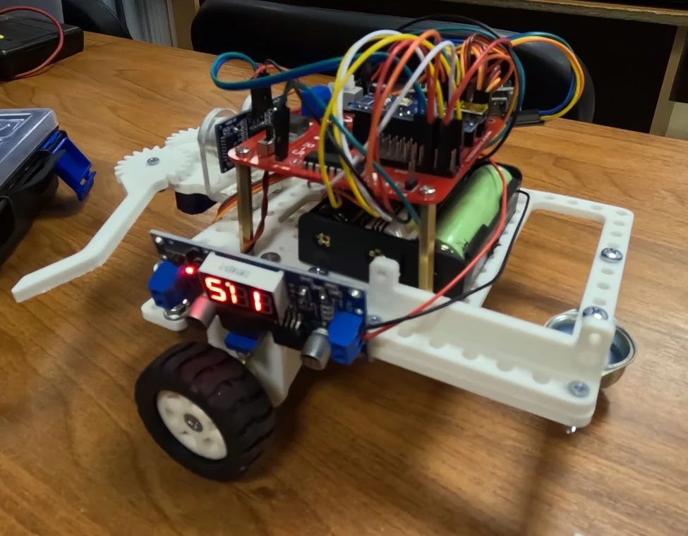
While assembly is in progress, the battery compartment is disconnected and the USB cable is not connected to the computer. The battery compartment is connected to the shield in advance by an adult. You turn the motors on and off only with a switch.
Assign roles
3 minWhat should a robot do. First, the robot needs to correctly execute individual commands: rotate each wheel, stop and report sensor readings. Before our independent trip, we will check each component in turn to look for the cause of the error in one place.
What we use and how it works. Arduino Uno is executing the program. The L298P driver uses its signals to control the power supply to the motors: the DIR pin sets the direction, PWM - the proportion of power supply time. The motor converts electrical energy into rotation, and the wheel into movement. Two reflection sensors on the bottom help distinguish between a light surface and a black line.
How to link a dimension to an action. The command and the result are two different things. The inscription in the monitor means that the program has reached printing; We check the rotation with our eyes. On the stand, we will check both directions of each wheel and the stop, then compare the readings of the sensors above the white and black cards. This way we’ll find out exactly how our robot is assembled.
You are working together. One - Pilot: holds parts and a screwdriver. Second - Navigator: reads the step out loud, provides the details and checks the result using the picture.
- Decide who starts as Pilot.
- After each part that is secured with screws, switch roles.
Everyone knows their role. The navigator holds the instructions, the pilot holds the instrument.
Lay out the parts
7 minFind every part before assembling. This way you won’t confuse similar parts and will immediately see if something is missing.
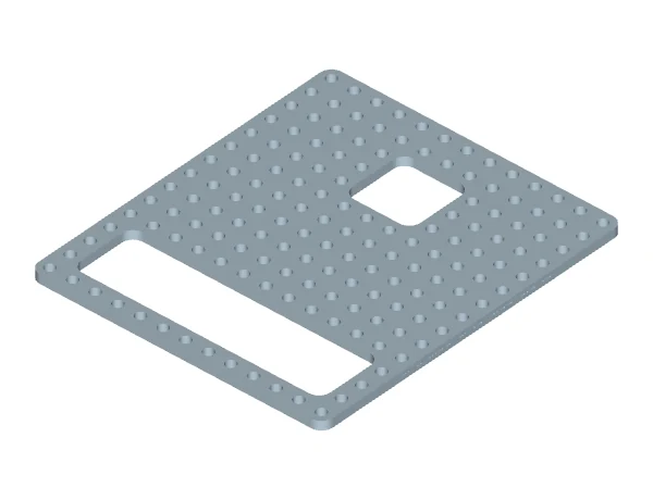
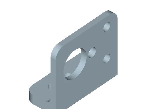
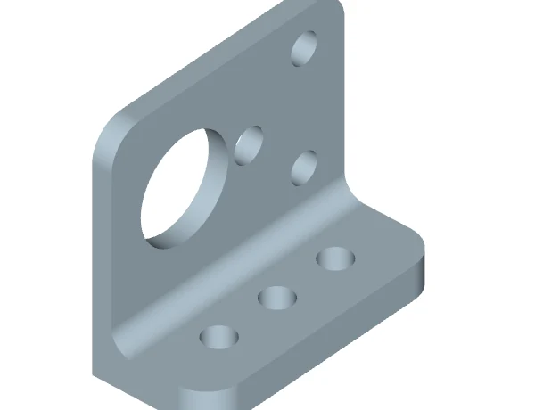
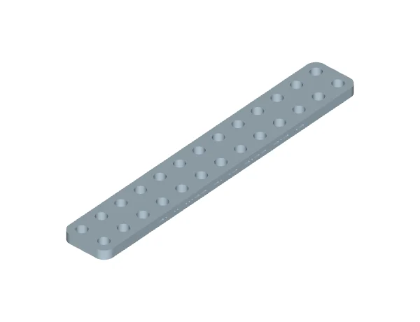
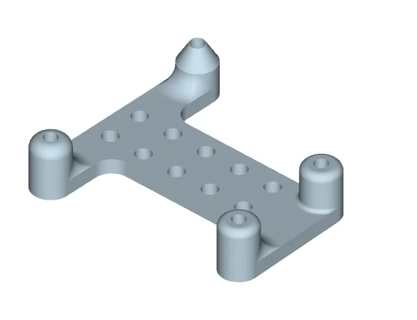
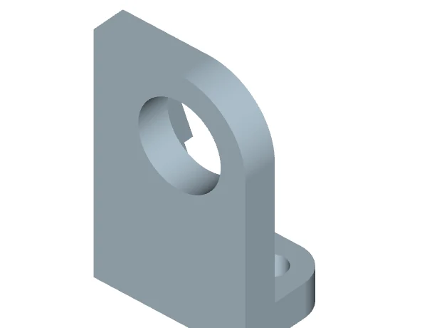
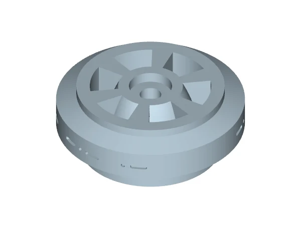
- Arrange the printed parts in a row, like on cards.
- Find two motor brackets. They are similar, but mirrored: put them side by side and look - the shelves face in different directions.
- Place the purchased parts nearby: Arduino, motor shield, two motors, a ball joint, two line sensors, a battery compartment and bags with fasteners.
All the details are in front of you. You can show both mirror brackets.
Hint: Missing part
Don't replace it with something similar. Check the package with cards again; If there are no details, tell an adult.
Practice on one screw
4 minAlmost all parts of the robot are held on by screws and nuts. Let's assemble one connection on the table.
- Take a screw, two washers and a nut from the Training bag.
- Place the washer on the screw, slide the screw through the two pieces, put the second washer on and screw the nut on with your fingers.
- Hold the nut with your finger and tighten the screw with a screwdriver. Stop as soon as the parts stop moving.
Connection order: screw → washer → part → part → washer → nut. The parts don't wobble.
How it works: Why you can’t tighten it with all your might
The parts are printed from plastic. If you overtighten the screw, the plastic will press through or crack. A sign of overtightening - the part bends or turns white around the screw.
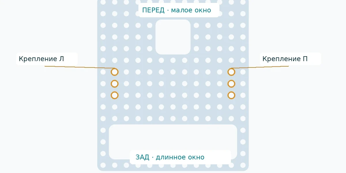
Agree where in front
3 minSo that “left wheel” always means the same thing, let’s mark the front of the robot.
- Lay the base flat: a small square window is further away from you, a long rectangular window is closer.
- Far side - before. Stick a paper forward arrow on it.
- Define left and right as the driver who sits in the robot and looks in the direction of the arrow.
There is a forward arrow on the base. You both show the left side of the robot the same way.
Attach the motor brackets
8 minBrackets hold the motors from the bottom of the base.
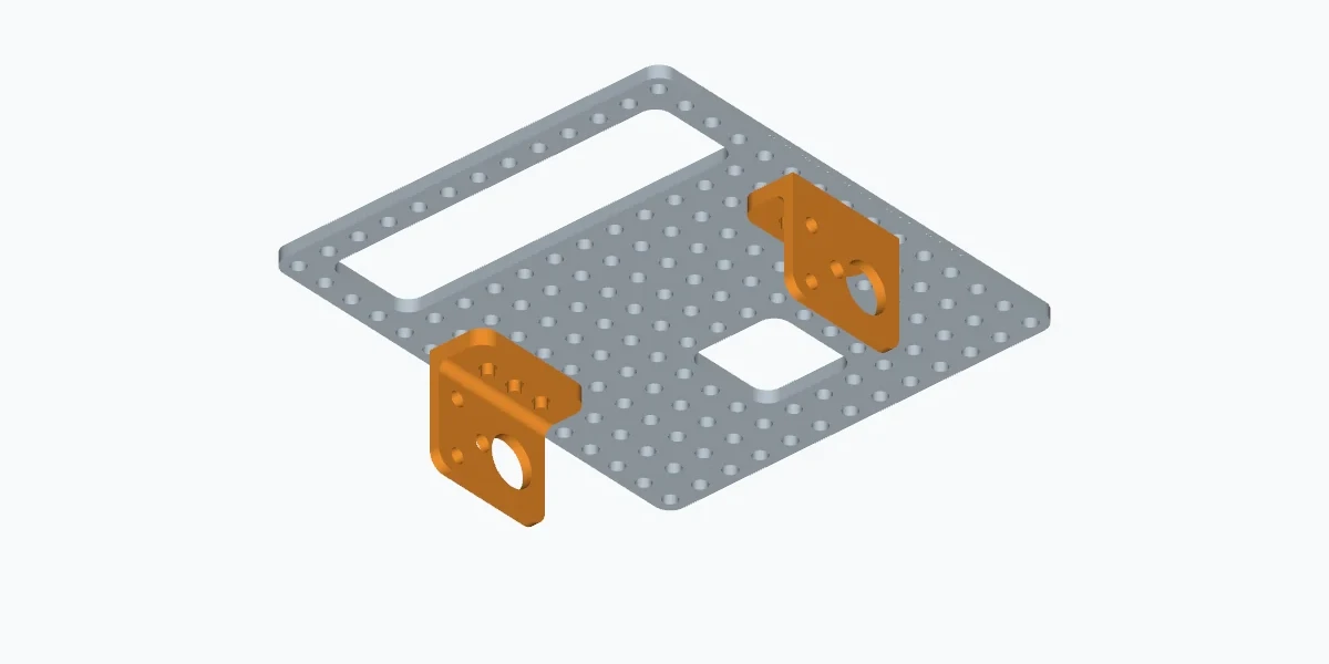
- Turn the base over so that the arrow remains visible from the side.
- Place the brackets on the bottom side as shown. Big round holes look out out - the wheel axles will go there.
- Insert the screws from above and fit the washers and nuts underneath. Start all screws loosely by hand, then tighten them.
The two brackets are facing each other, the large holes are on the outside. The brackets do not swing.
Install the motors
8 minThe motor axis is a rotating rod on which the wheel fits. It should come out through the hole in the bracket.
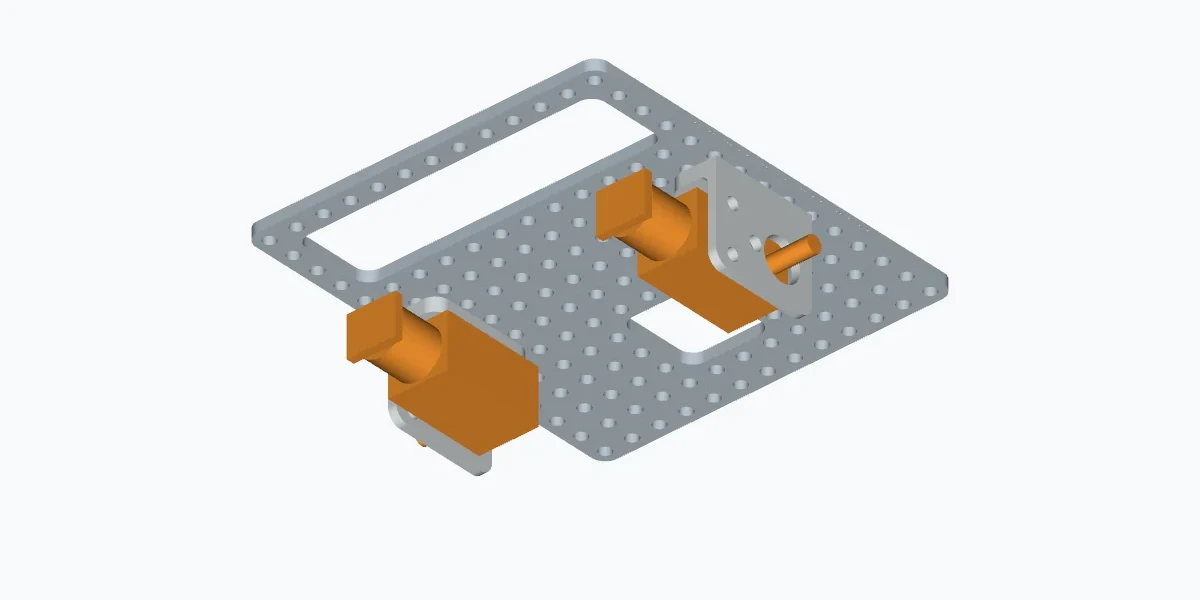
- Attach the first motor to the bracket from the inside. The axis passes through a large hole outward.
- Secure the motor with the screws from the Motors package. Hold the motor with your hand while you tighten it.
- Also install the second motor.
- Label the wires: L - left motor, P - right. Check the forward arrow.
Both motors are held tightly, the axes point left and right, the wires are labeled.
Hint: The motor does not fit into the bracket
Don't press or file. Check if this is the right bracket: maybe you took a mirror one for the other side.
Put on the wheels
5 min- Align the wheel hole with the motor axle. The shape of the hole must match the shape of the axis.
- Put the wheel on while holding the motor by the housing. Don't hit the wheel.
- Look from the side: the wheel should not touch the bracket or base.
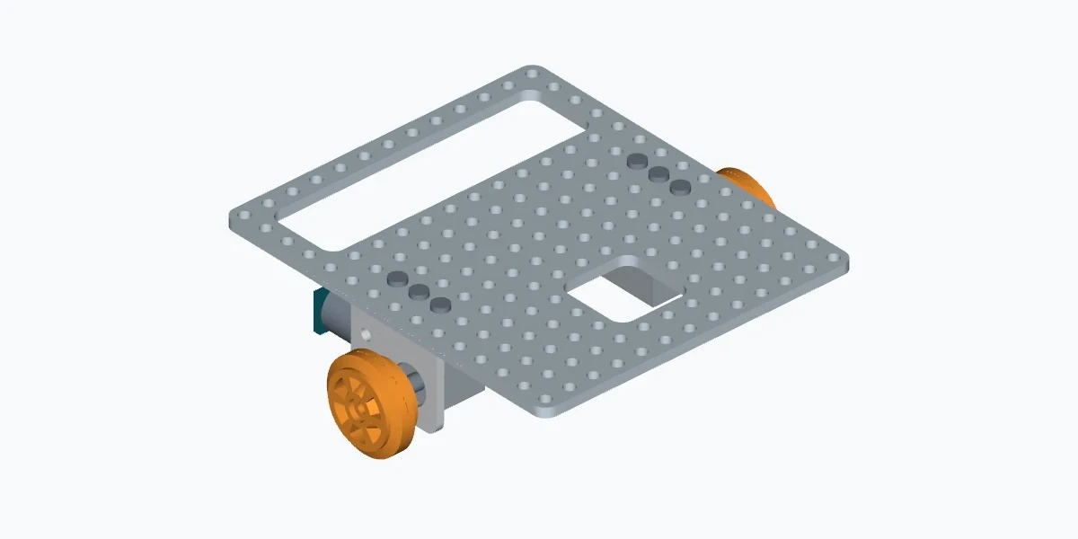
Two wheels stand on axles and do not touch anything.
Add a back support and check the robot
7 minThere are two wheels, so the robot needs a third support point at the back - a ball joint.
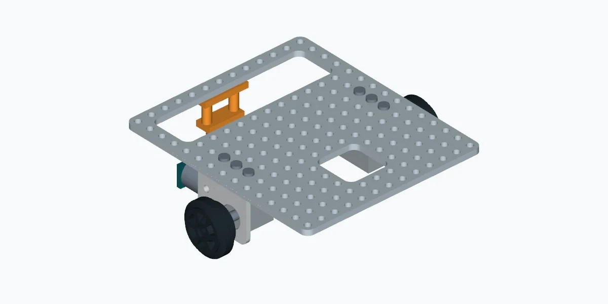
- Attach the ball joint from below to the back side of the base. The racks from the “Support” package are selected in height.
- Place the robot on the table. It should stand exactly on two wheels and a support.
- Gently rock the robot. Nothing should be loose.
The robot stands stable and level. The chassis is ready.
Install Arduino
6 minArduino is the “brain” of the robot. The board lies on the holder so that its contacts from below do not touch the screws.
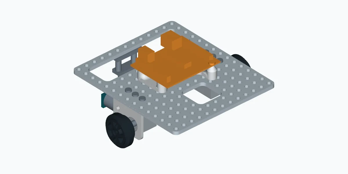
- Secure the Arduino holder in the center of the base with the posts facing up.
- Place the board on the stands so that the USB connector is at the edge and can be reached.
- Secure the board with screws. Tighten them one by one, little by little.
The board lies flat and does not touch the base screws. The USB connector is free.
Prepare your computer
5 minPrograms for the robot are written in MyRobotica. It has lessons and a code editor.
- Connect the USB cable to the Arduino and to the computer. The battery compartment of the motors remains disconnected.
- Open MyRobotica course "Robot Courier" and lesson 1.1. Open the lesson project.
- On the right side of the button Upload to robot choose your real robot. B More about communication check the board Arduino Uno and its port.
- Leave empty functions in the editor
setup()andloop()and save the program.
The ON power indicator on the board is lit. In MyRobotica, the tutorial project is open, a real robot with an Arduino Uno board is selected, and its port is visible.
Hint: I don't see the port
Disconnect and reconnect the cable. If the port still does not appear, the cable may only charge and not transmit data. Ask for another cable.
Programs for the robot are written in MyRobotica. It has lessons and a code editor.
- Connect the USB cable to the Arduino and to the computer. The battery compartment of the motors remains disconnected.
- Open MyRobotica course "Robot Courier", lesson 1.1 and his study project.
- On the right side of the button Upload to robot choose your real robot. Open up More about communication and check the board Arduino Uno. Unplug the USB cable, see how the connection status changes, and plug it in again. Log the port name.
- Leave empty functions in the editor
setup()andloop()and save the program.
A tutorial project is opened in MyRobotica and a real robot with an Arduino Uno board is selected. Its port name is recorded.
Hint: The port never appeared
The cable can only charge and not transmit data. Ask for another cable.
- Connect the USB cable to the Arduino and to the computer. The battery compartment of the motors remains disconnected.
- Open a course in MyRobotica "Robot Courier", lesson 1.1 and his educational project. On the right side of the button Upload to robot choose your real robot. Via More about communication check the board Arduino Uno and find its port.
- Save the program with empty
setup()andloop(), click Check code, and then Upload to robot. - Write down in the log: board, port, MyRobotica version and what Check code is different from Upload to robot - what each button does and whether a board is needed for it.
The empty sketch has been verified and uploaded. The logbook contains the board, port, MyRobotica version and the difference between the two buttons.
Hint: Check the code and Upload to the robot
Disconnect the cable and press both buttons in turn. Which one worked without paying?
Check program upload
3 minUpload an empty sketch and read the message about the successful upload.
void setup() {} void loop() {}
This tests the board, USB connection and uploading. It does not yet establish that the motors, shield, sensors or mechanical assembly work correctly. We will test their operation after connecting all components.
Put on the shield and connect the motors
7 minArduino pins cannot supply enough current to motors. Therefore, the motors are connected to shield - a board that is placed on top of the Arduino and turns on the motors according to its commands.
First, unplug the USB cable. Do not connect or disconnect anything while the board is powered.
- Align the shield legs with the Arduino sockets and gently press on top. No leg should be left out or bent.
- Connect the motor wires to the shield terminals:
| What we connect | Where |
|---|---|
| Left motor Label the wires with the letter "L". | M2 channel terminals on the shield |
| Right motor Label the wires with the letter "P". | Channel M1 terminals on the shield |
| Battery compartment (via switch)adult An adult connects. | Motor power terminals on the shield |
- The battery compartment with the switch is already connected by an adult. Check that the switch is off. If the compartment wires are not connected, do not connect them yourself, call an adult.
The shield sits flat on the Arduino. The motor wires are secured in terminals and labeled.
Install line sensors
6 minLine sensors will "look" at the floor and notice a black line. We place them in front, across the robot.
- Attach the sensor strip from the bottom at the front edge of the base to the posts.
- Attach two sensors to the bar - left and right - with the sensitive side down, to the floor. The sensors are at the same height.
- Connect the sensors to the shield according to the table. The letters of the sensor contacts are: S - signal, V - power, G - ground.
| What we connect | Where |
|---|---|
| Left sensor S (signal) | A4 |
| Left sensor V (power) | 5V |
| Left sensor G (ground) | GND |
| Right sensor S (signal) | A5 |
| Right sensor V (power) | 5V |
| Right sensor G (ground) | GND |
- Lay the wires so that they do not touch the wheels.
Two sensors face down, their wires are connected and do not hang down to the wheels.
Check all robot components
14 minNow let's check that every part of the robot works: both wheels and both sensors. The verification program is already open in the editor on the right.
Place the robot on the stand so that the wheels hang in the air and do not touch the table. While the motor switch is off, the wheels cannot spin.
There is no need to write a program - it is ready. You will send her letters and numbers, and she will spin one wheel or show the numbers of the sensors.
// Программа проверки для робота курса (Arduino Uno + шилд L298P).// Робот стоит на подставке: колёса висят в воздухе.// Колесо крутится со скоростью 120 из 255 около 0,3 секунды.const int LEFT_DIR = 7;const int LEFT_PWM = 6;const int RIGHT_DIR = 4;const int RIGHT_PWM = 5;const int LEFT_SENSOR = A4;const int RIGHT_SENSOR = A5;const int FORWARD = HIGH;const int BACKWARD = LOW;const int TEST_PWM = 120;const unsigned long PULSE_MS = 300;bool running = false;unsigned long startedAt = 0; void reportSensors() { Serial.print("LEFT="); Serial.print(analogRead(LEFT_SENSOR)); Serial.print(" RIGHT="); Serial.println(analogRead(RIGHT_SENSOR));} void beginPulse(int dirPin, int pwmPin, int direction) { digitalWrite(dirPin, direction); analogWrite(pwmPin, TEST_PWM);} // ===== Готовая оболочка — не меняй =====void stopMotors() { analogWrite(LEFT_PWM, 0); analogWrite(RIGHT_PWM, 0); running = false;} void setup() { pinMode(LEFT_PWM, OUTPUT); pinMode(RIGHT_PWM, OUTPUT); stopMotors(); pinMode(LEFT_DIR, OUTPUT); pinMode(RIGHT_DIR, OUTPUT); pinMode(LEFT_SENSOR, INPUT); pinMode(RIGHT_SENSOR, INPUT); Serial.begin(9600); Serial.println("READY: 1=L forward, 2=L backward, 3=R forward, 4=R backward, d=sensors, s=stop");} void loop() { if (running && millis() - startedAt >= PULSE_MS) { stopMotors(); Serial.println("PWM=0; verify physical stop"); } if (!Serial.available()) return; char command = Serial.read(); if (command == 's') { stopMotors(); Serial.println("PWM=0; verify physical stop"); return; } // Пока идёт импульс, новые команды не продлевают и не перезапускают его. if (running) return; if (command == 'd') { reportSensors(); return; } if (command < '1' || command > '4') return; // Удаляем накопленные команды: один ввод не должен запускать очередь движений. while (Serial.available()) Serial.read(); stopMotors(); startedAt = millis(); running = true; if (command == '1') beginPulse(LEFT_DIR, LEFT_PWM, FORWARD); if (command == '2') beginPulse(LEFT_DIR, LEFT_PWM, BACKWARD); if (command == '3') beginPulse(RIGHT_DIR, RIGHT_PWM, FORWARD); if (command == '4') beginPulse(RIGHT_DIR, RIGHT_PWM, BACKWARD); Serial.println("Observe wheel; no automatic hardware PASS");}
How it works: What the program does
reportSensorsprints two numbers: what the left and right sensor sees.beginPulseincludes one wheel.- After 0.3 seconds the wheel stops itself: this does
stopMotors.
Everything in the program is already ready, except for two functions in the “Your part” section. Add them:
reportSensors— prints the numbers of the left and right sensor with captions;beginPulse- turns the selected motor in the desired direction at speedTEST_PWM. The second motor is turned off.
Don't change the rest of the program.
// Программа проверки для робота курса (Arduino Uno + шилд L298P).// Робот стоит на подставке: колёса висят в воздухе.// Колесо крутится со скоростью 120 из 255 около 0,3 секунды.const int LEFT_DIR = 7;const int LEFT_PWM = 6;const int RIGHT_DIR = 4;const int RIGHT_PWM = 5;const int LEFT_SENSOR = A4;const int RIGHT_SENSOR = A5;const int FORWARD = HIGH;const int BACKWARD = LOW;const int TEST_PWM = 120;const unsigned long PULSE_MS = 300;bool running = false;unsigned long startedAt = 0; // ===== Твоя часть =====void reportSensors() { // Цель: показать в мониторе подписанные показания левого и правого датчиков.} void beginPulse(int dirPin, int pwmPin, int direction) { // Цель: включить только указанный мотор с указанным направлением и TEST_PWM.} // ===== Готовая оболочка — не меняй =====void stopMotors() { analogWrite(LEFT_PWM, 0); analogWrite(RIGHT_PWM, 0); running = false;} void setup() { pinMode(LEFT_PWM, OUTPUT); pinMode(RIGHT_PWM, OUTPUT); stopMotors(); pinMode(LEFT_DIR, OUTPUT); pinMode(RIGHT_DIR, OUTPUT); pinMode(LEFT_SENSOR, INPUT); pinMode(RIGHT_SENSOR, INPUT); Serial.begin(9600); Serial.println("READY: 1=L forward, 2=L backward, 3=R forward, 4=R backward, d=sensors, s=stop");} void loop() { if (running && millis() - startedAt >= PULSE_MS) { stopMotors(); Serial.println("PWM=0; verify physical stop"); } if (!Serial.available()) return; char command = Serial.read(); if (command == 's') { stopMotors(); Serial.println("PWM=0; verify physical stop"); return; } // Пока идёт импульс, новые команды не продлевают и не перезапускают его. if (running) return; if (command == 'd') { reportSensors(); return; } if (command < '1' || command > '4') return; // Удаляем накопленные команды: один ввод не должен запускать очередь движений. while (Serial.available()) Serial.read(); stopMotors(); startedAt = millis(); running = true; if (command == '1') beginPulse(LEFT_DIR, LEFT_PWM, FORWARD); if (command == '2') beginPulse(LEFT_DIR, LEFT_PWM, BACKWARD); if (command == '3') beginPulse(RIGHT_DIR, RIGHT_PWM, FORWARD); if (command == '4') beginPulse(RIGHT_DIR, RIGHT_PWM, BACKWARD); Serial.println("Observe wheel; no automatic hardware PASS");}
Hint: Where to start
Find it in Arduino Help analogRead, Serial.print, digitalWrite and analogWrite. Check the sensors first - you don't need motors for this.
Write the program yourself. The blank contains only contact numbers and turning off the motors.
// Программа проверки для робота курса (Arduino Uno + шилд L298P).// Робот стоит на подставке: колёса висят в воздухе.// Колесо крутится со скоростью 120 из 255 около 0,3 секунды.const int LEFT_DIR = 7;const int LEFT_PWM = 6;const int RIGHT_DIR = 4;const int RIGHT_PWM = 5;const int LEFT_SENSOR = A4;const int RIGHT_SENSOR = A5;const int FORWARD = HIGH;const int BACKWARD = LOW;const int TEST_PWM = 120;const unsigned long PULSE_MS = 300;bool running = false;unsigned long startedAt = 0; // Напиши диагностику по требованиям урока. При включении моторы стоят.void setup() { pinMode(LEFT_PWM, OUTPUT); pinMode(RIGHT_PWM, OUTPUT); analogWrite(LEFT_PWM, 0); analogWrite(RIGHT_PWM, 0);} void loop() {}
What the program should be able to do:
- work with Serial Monitor at speed 9600;
- by letter
dprint signed numbers of both sensors; - by
1and2turn the left wheel forward and backward,3and4- right; - spin each time at speed 120 for no longer than 300 ms, then turn off both motors;
- by letter
sturn off both motors at once, even during rotation; - after turning on and the Reset button, the motors stand until a new command arrives;
- extra clicks do not accumulate in the queue and do not prolong the rotation.
Hint: How to do without delay
Remember the start time of rotation through millis(). In every aisle loop() check if she has arrived s and whether 300 ms has passed.
How to check a robot
- Check the wires. The motor switch is off. Check the wires with the connection tables: each one is in its place and does not touch the wheels. The wheels rotate freely by hand.
- Upload the program. Click Upload to robot. Open downstairs Serial Monitor at 9600 speed. The line
READY- the board responds. Press the Reset button on the board: the wheels stop. - Check the sensors. Submit
dand read the two numbers. Place white paper under the left sensor and sendd, then black - and againd. Do the same with the right sensor. On white and black, the numbers should be noticeably different. - Check the wheels. Turn on the motor switch. Send
1and look at the wheels: only the left wheel turns forward briefly and stops itself. Then send one by one2,3and4. - Check the stop. Submit
1and immediatelys- the wheel stops. Turn off the motor switch and send1once again: the wheels don't spin. - Write down the result to log for each component from the table: command, response in Serial Monitor and actual rotation or sensor reading. If the component has not yet been verified, write down “not verified.” If something is wrong, turn off the motor switch, disconnect the USB, open “If it doesn’t work”, fix it and check this unit again.
| What we check | What to do | It's good if |
|---|---|---|
| Fee | Load the program, click Reset | Yes READY, the wheels are standing |
| Left wheel | Submit 1, then 2 | Only the left one rotates: forward, then back |
| Right wheel | Submit 3, then 4 | Only the right one rotates: forward, then back |
| Left sensor | d on white and black | The numbers are noticeably different |
| Right sensor | d on white and black | The numbers are noticeably different |
| Stop | s and motor switch | The wheel stops |
| What do you see | What to do (motor switch is off) |
|---|---|
| The wrong wheel is spinning | Swap the motor wires at terminals M1 and M2 |
| The wheel spins backwards instead of forwards | Swap the two wires of this motor in the terminal |
| The wheel doesn't spin | Check that the switch is on and the wires are tightly clamped to the terminals |
| The sensor number does not change | Check the S, V, G wires and the height of the sensor above the floor |
No line READY | Check the speed of 9600 and the selected port |
| The wheel spins on its own after Reset | Check that this is the program loaded |
| Nothing helps | Call an adult and show where you stopped |
You checked each wheel in both directions, both sensors and the stop. The results are recorded in a table.
Write the result in the journal
4 min- Write down the date, the robot's name and what happened today in the logbook.
- Note which components passed the test immediately and which ones you corrected.
- Save the check program - it will come in handy if the robot starts behaving strangely.
The robot has been checked, the results are recorded in the log, the verification program is saved.
Test yourself
Select answers to prepare. They are not stored or evaluated on the site. Take the knowledge test in the course syllabus or discuss the answers with your instructor.
● Basic
★ Intermediate level
★★ Advanced level
Answer questions at your level. Correct answers needed: Beginner - 4 out of 5; Average - 4 out of 5; Advanced - 4 out of 5. Answers will be checked by the teacher or course program.
Summary
You assembled the robot's chassis, installed the board and sensors, and wrote the first program. You confirmed the operation of the installed components with observations. Knowledge testing is required separately. In the next lesson you will move from individual tests on the stand to controlled movement.
How to confirm the result
For each experiment, save the conditions, program version, observation and conclusion. When comparing attempts, change one reason at a time; unsuccessful attempts also remain in the log. Marking a result refers to actions that have already been completed; there is no need to repeat them for the sake of marking. If the result is not obtained, write down the discrepancy and the next hypothesis to be tested. A model, measurements of a real robot, and an explanation are different types of evidence.
Lesson vocabulary
| Arduino | A board with a microcontroller - a small computer that runs your program. |
| shield | A board that fits on top of the Arduino and adds capabilities to it. Our shield controls the motors. |
| sketch | Program for Arduino. |
| function | Named command block. setup and loop are functions. |
| LED | Small light bulb on the board. LED L is connected to pin 13. |
| output | A board pin that a program can control or read a signal from. |
| ms | Millisecond is a thousandth of a second. 1000 ms = 1 second. |